
Method of reducing combustion induced oscillations in turbine engine

A technology of turbine engine and combustion chamber, which is applied in the direction of combustion method, engine function, engine control, etc., and can solve problems such as mechanical fatigue of engine components, adverse effects of engine, thermal fatigue, etc.

Inactive Publication Date: 2015-02-25
SOLAR TURBINES
View PDF7 Cites 1 Cited by
  • Summary
  • Abstract
  • Description
  • Claims
  • Application Information

AI Technical Summary

Problems solved by technology

Depending on the magnitude of the oscillations, these oscillations can lead to mechanical and thermal fatigue of engine components or other adverse effects on the engine

Method used


Image

  • Method of reducing combustion induced oscillations in turbine engine
  • Method of reducing combustion induced oscillations in turbine engine
  • Method of reducing combustion induced oscillations in turbine engine

Examples


Embodiment Construction

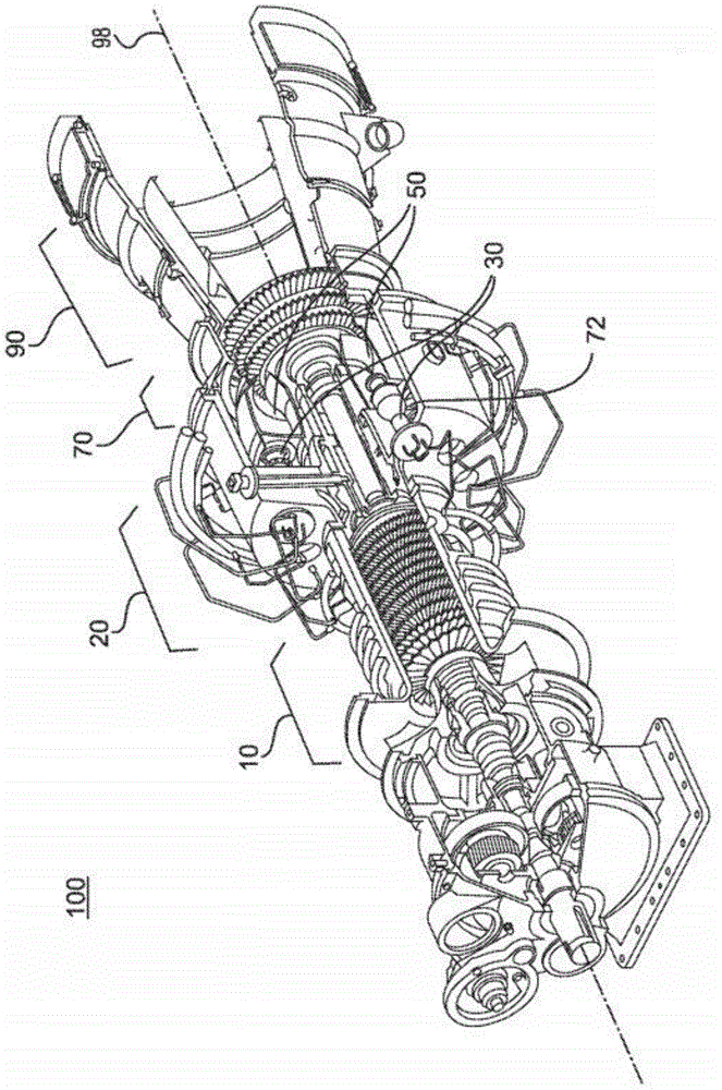
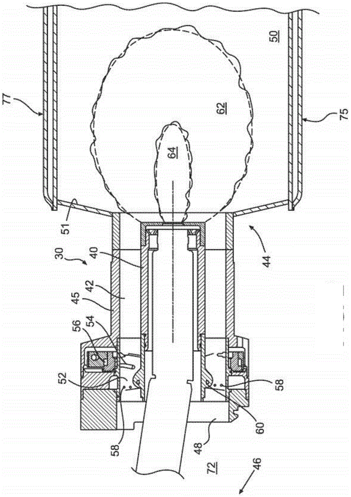
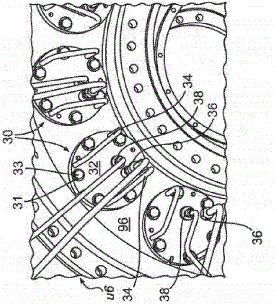
[0017] figure 1 An exemplary gas turbine engine (GTE) 100 is shown. GTE 100 may have, among other systems, compressor system 10 , combustor system 20 , turbine system 70 and exhaust system 90 arranged along engine axis 98 . Compressor system 10 compresses air and delivers the compressed air to enclosure 72 of combustor system 20 . Compressed air is directed from the enclosed volume 72 into one or more fuel injectors 30 positioned therein. The compressed air is mixed with fuel in fuel injector 30 , and the fuel-air mixture is directed to a combustion chamber (combustion chamber 50 ). The fuel air mixture is ignited and combusted in the combustor 50 to produce high pressure and high temperature combustion gases. These combustion gases are then directed to turbine system 70 . A turbine system 70 extracts energy from these combustion gases and directs the exhaust gases to the atmosphere through an exhaust system 90 .

[0018] Liquid fuel (eg, diesel, kerosene, etc.) or gaseou...


PUM


Abstract

Systems and methods for operating a turbine engine having a plurality of fuel injectors arranged circumferentially in a combustor, with each fuel injector having a main fuel supply and a pilot fuel supply, includes supplying fuel to the plurality of fuel injectors through the main fuel supply to create a circumferential thermal gradient in the combustor.

Description

technical field [0001] The present disclosure generally relates to systems and methods for reducing combustion-induced oscillations in gas turbine engines. Background technique [0002] Gas turbine engines generate power by extracting energy from hot gases produced by the combustion of a fuel-air mixture. Combustion of hydrocarbon fuels produces pollutants such as NOx. Gas turbine engine manufacturers have developed several technologies (lean premixed combustion, etc.) to reduce NOx. However, an undesired side effect of this type of technique is a form of combustion instability such as thermoacoustic oscillations in the combustion chamber. These oscillations arise due to a combination of heat release and pressure waves, and resonate at the natural frequency of the combustion chamber. This phenomenon is described by the well-known Rayleigh Mechanism. Depending on the magnitude of the oscillations, these oscillations can lead to mechanical and thermal fatigue of engine com...

Claims


Application Information

Patent Timeline
Patent Type & Authority Applications(China)
IPC IPC(8): F02C7/00F02C7/22F02C3/14
CPCF02C7/228F05D2260/964F23R3/28F23R3/346F23R2900/00013F23R3/343F05D2270/14F02C7/222F02C3/14F02C7/00F02C7/22
Inventor M·E·阿布勒
Owner SOLAR TURBINES
Learn More