
Organic electroluminescent element, organic electroluminescent lighting device, and organic electroluminescent display device

一种电致发光元件、致发光的技术,应用在电致发光光源、照明装置、电气元件等方向,能够解决产生浓度分布、溶解性差、电荷输送材料与发光材料溶解性差等问题,达到驱动电压低、电能效率高的效果

Active Publication Date: 2015-02-25
MITSUBISHI RAYON CO LTD
View PDF25 Cites 7 Cited by
  • Summary
  • Abstract
  • Description
  • Claims
  • Application Information

AI Technical Summary

Problems solved by technology

In addition, when the light-emitting layer is formed by a wet film-forming method as in the present invention, due to the difference in solubility between the charge-transporting material and the light-emitting material, etc., it is impossible to mix uniformly or to precipitate uniformly during film formation and drying, resulting in aggregation of various materials. , there are problems such as the reduction of the luminous efficiency of the component
[0018] In addition, due to the poor solubility of materials other than charge transport materials such as luminescent materials, uniform mixing cannot be achieved or concentration distribution occurs during film formation, which may cause problems such as luminous efficiency.

Method used


Image

  • Organic electroluminescent element, organic electroluminescent lighting device, and organic electroluminescent display device
  • Organic electroluminescent element, organic electroluminescent lighting device, and organic electroluminescent display device
  • Organic electroluminescent element, organic electroluminescent lighting device, and organic electroluminescent display device

Examples


Embodiment 1

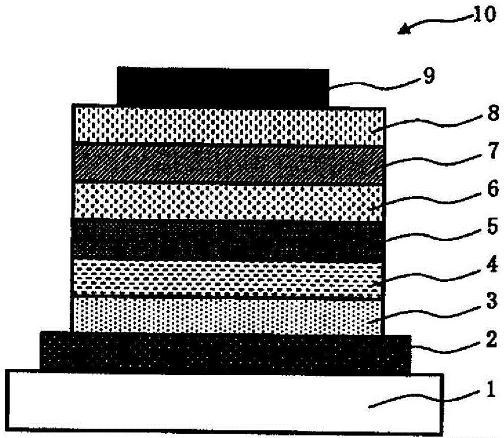
[0611] An organic electroluminescent element was produced in the following steps.

[0612] After depositing an indium tin oxide (ITO) transparent conductive film on the glass substrate 1 by sputtering, a common photolithography technique and hydrochloric acid etching were used to pattern 2 mm wide stripes to form the anode 2 . After patterning, the ITO substrate is cleaned in the order of ultrasonic cleaning with aqueous surfactant solution, water washing with ultrapure water, ultrasonic cleaning with ultrapure water, and water washing with ultrapure water, then dried, and then UV ozone cleaning .

[0613] Next, a polymer containing arylamine shown in the following structural formula (P-1), 4-isopropyl-4'-methyldiphenyliodonium tetrakis( A composition for forming a hole injection layer having the following composition of pentafluorophenyl) borate and ethyl benzoate. The composition for forming a hole injection layer was formed into a film on the anode 2 by spin coating under...

Embodiment 2

[0654] Using compounds (H-1), (E-1) and compound (H-2) shown below as the charge transporting material of the composition for forming a light-emitting layer, a composition for forming a light-emitting layer prepared with the following composition was used, except Otherwise, an organic electroluminescence element was fabricated in the same manner as in Example 1. The properties of the obtained elements are listed in Table 1.

[0655] [chem 79]

[0656]

[0657]

[0658]

Embodiment 3

[0660] Compounds (H-1), (E-1) and compound (H-3) shown below were used as the charge transport material of the composition for forming a light-emitting layer, and compound (B2) shown below was used instead of the compound of the light-emitting material (B1) Except having used the composition for light emitting layer formation prepared by the following composition, it carried out similarly to Example 1, and produced the organic electroluminescent element. The properties of the obtained elements are listed in Table 1.

[0661] [chem 80]

[0662]

[0663]

[0664]


PUM

PropertyMeasurementUnit
boiling pointaaaaaaaaaa
glass transition temperatureaaaaaaaaaa
boiling pointaaaaaaaaaa

Abstract

An organic electroluminescent element which comprises a positive electrode, a negative electrode and a light emitting layer that is arranged between the positive electrode and the negative electrode. This organic electroluminescent element is characterized in that: at least the light emitting layer is formed by a wet film-forming method; the light emitting layer contains a charge transport material and a light emitting material; the charge transport material contains a hole transport material and an electron transport material, each having a specific partial structure; the light emitting material is composed of at least three kinds of materials and has at least two maximum emission wavelengths in the emission spectrum; and the organic electroluminescent element has a hole injection / transport layer between the positive electrode and the light emitting layer such that the hole injection / transport layer is adjacent to the light emitting layer.

Description

technical field [0001] The invention relates to an organic electroluminescence element, an organic electroluminescence lighting device and an organic electroluminescence display device. Background technique [0002] Since Kodak Corporation released a layered organic electroluminescence (electroluminescence: hereinafter sometimes abbreviated as "EL") element using a vapor deposition method, organic EL displays have been extensively developed and are now being put into practical use. [0003] In such a layered organic electroluminescence element, two or more organic layers (light emitting layer, hole injection layer, hole transport layer, electron transport layer, etc.) are provided between an anode and a cathode in a laminated manner. This laminated organic electroluminescent element is self-luminous, so it has a wide viewing angle and high visibility, and because it is a thin film type, it saves space. From these points of view, this laminated organic electroluminescence Li...

Claims


Application Information

Patent Timeline
Patent Type & Authority Applications(China)
IPC IPC(8): H01L51/50C07C211/61C07D401/14C07D403/10C07D403/14C07D405/10C07D405/14C07D409/14C07F15/00C09K11/06G09F9/30H01L27/32
CPCH01L51/5036H01L51/0085C07D403/14C07D409/14H01L51/5088C09K2211/1416C07D401/14C09K2211/1007C09K11/06H01L51/0073C07D403/10H01L2251/5384C09K2211/1433H01L51/5016H01L51/0035H01L51/0067C09K2211/1425H01L51/0072C09K2211/1029C09K2211/1092C07D405/10C07C211/54C09K2211/1037H01L51/0039C09K2211/185C07C211/61H05B33/14C07D405/14H01L51/0043H10K85/115H10K85/111H10K85/151H10K85/654H10K85/6574H10K85/342H10K85/6572H10K50/125H10K50/17H10K50/11H10K2101/10H10K2101/90Y02B20/00C07F15/00Y10S428/917H10K50/00H10K71/00H10K85/40H10K85/615H10K85/6576H10K50/15H10K50/16
Inventor 鹤谷泰之五郎丸英贵今田一郎
Owner MITSUBISHI RAYON CO LTD
Learn More