Eureka AIR delivers breakthrough ideas for toughest innovation challenges, trusted by R&D personnel around the world.

Two-plate mold closing machine for moving molds in one direction

A two-plate type, clamping machine technology, applied in the field of clamping machines, can solve the problems of high energy consumption, short service life, large volume, etc., achieve uniform pressure distribution, reduce damage and wear

Inactive Publication Date: 2015-03-04
宁波顺兴机械制造有限公司
View PDF8 Cites 4 Cited by
  • Summary
  • Abstract
  • Description
  • Claims
  • Application Information

AI Technical Summary

Problems solved by technology

[0003] The traditional mold clamping machine is a three-plate mold clamping machine with an upper base, a middle base and a lower base. The mold clamping cylinder plays the role of quickly driving the middle base and high-pressure mold clamping. Since the mold clamping cylinder has a large mold clamping effect, the volume is small. It is relatively large, and the stroke is large, and the energy consumption is also large. The hydraulic oil circulates and exchanges in the oil cylinder, which causes the oil temperature to rise rapidly, causing the hydraulic parts to be damaged quickly and the service life is not long.
Moreover, the height of the three-plate mold clamping machine is very high, and some factories cannot be equipped due to height restrictions.

Method used


Image

  • Two-plate mold closing machine for moving molds in one direction
  • Two-plate mold closing machine for moving molds in one direction
  • Two-plate mold closing machine for moving molds in one direction

Examples


Embodiment

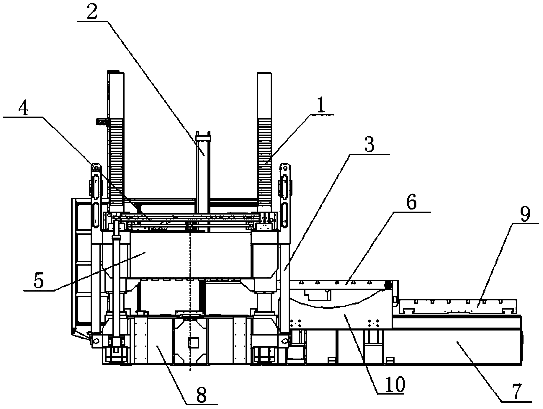
[0027] There are 4 high-pressure mold-clamping oil cylinders, which form a square and are arranged in the middle of the lower seat. During high-pressure mold-locking, they are pressed against the lower template moved in to play a high-pressure mold-locking role. The upper part of the mold acts as a clamping force.

[0028] The upper base 5 slides up and down along the pull rod through the fast oil cylinder 3 at the lower end, and the brake nut 12 at the upper end of the upper base 5 realizes the simultaneous brake through the control of the brake synchronization device 4, so that the upper base 5 is fixed at a certain height on the pull rod , when the mold is opened, the mobile lower template 9 on the lower mold removal seat 7 first moves outward to one end of the lower mold removal seat 7, and then the turnover template 6 can be turned around the hinge through the action of the turning cylinder 2 and the upper seat 5 Rotate, one end of the flip template 6 slides along the cur...


PUM


Abstract

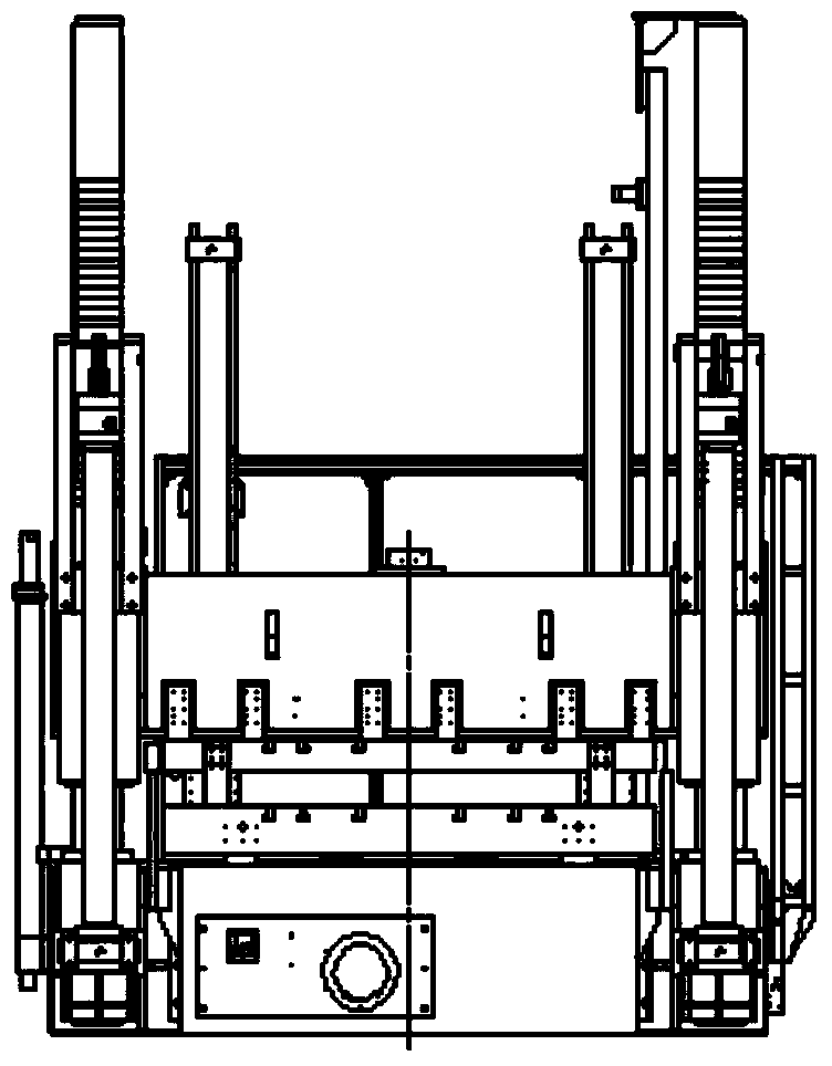
The invention relates to a two-plate mold closing machine for moving molds in one direction. The machine comprises a lower base, an upper base and a lower mold removing base, wherein pull rods are vertically mounted on four top angles of the lower base; the upper base is in sliding cup joint on the four pull rods; quick oil cylinders connected with the lower base are respectively mounted at the outer sides of the top angles of the upper base; brake nuts are mounted in the connected position of the upper end of the upper base and the pull rods; the two brake nuts at the two sides are connected through a brake synchronization device; the removing base is mounted at one side of the lower base; a movable lower template and an overturning template are mounted on the removing base in a sliding manner; and the removing directions of the movable lower template and the overturning template are one direction. Multiple high-pressure locking mold oil cylinders are vertically mounted in the lower base. The machine discards a traditional three-plate structure, reduces the body height, decreases the cost, and adds a flexible mold closing structure to enable the pressure between parting surfaces of the molds to become uniform.

Description

technical field [0001] The invention relates to the field of mold clamping machines, in particular to a two-plate mold clamping machine which moves molds in the same direction. Background technique [0002] The mold clamping machine is a professional mold research and matching equipment, which is mainly used for pressing and closing the upper and lower molds with different pressures during the later stage of mold making. It adopts a variety of reliable devices, equipped with mobile table mold clamping and positioning device, upward moving flip locking device, mechanical flipping device, hydraulic ejector pin, mold slide control, safety anti-falling device, etc. [0003] The traditional mold clamping machine is a three-plate mold clamping machine with an upper base, a middle base and a lower base. The mold clamping cylinder plays the role of quickly driving the middle base and high-pressure mold clamping. Since the mold clamping cylinder has a large mold clamping effect, the ...

Claims


Application Information

Patent Timeline
IPC IPC(8): B23P19/00
CPCB23P19/00
Inventor 叶佳杰
Owner 宁波顺兴机械制造有限公司
Why Eureka
Eureka Blog
Learn More