
Vehicle roll center position measuring device and calculating method of vehicle roll center position

A center position and measuring device technology, which is applied in the research field of vehicle rollover and rollover, can solve the problems affecting the accuracy and effect of the vehicle anti-rollover control system, and achieve the effect of improving the research accuracy and effect

Active Publication Date: 2015-03-04
SHANDONG JIAOTONG UNIV
View PDF6 Cites 11 Cited by
  • Summary
  • Abstract
  • Description
  • Claims
  • Application Information

AI Technical Summary

Problems solved by technology

However, when the car rolls and rolls over, its roll center position changes, and it will affect the accuracy and effect of the car anti-rollover control system. The current technical literature fails to realize the measurement of the car roll center position

Method used


Image

  • Vehicle roll center position measuring device and calculating method of vehicle roll center position
  • Vehicle roll center position measuring device and calculating method of vehicle roll center position

Examples


Embodiment 1

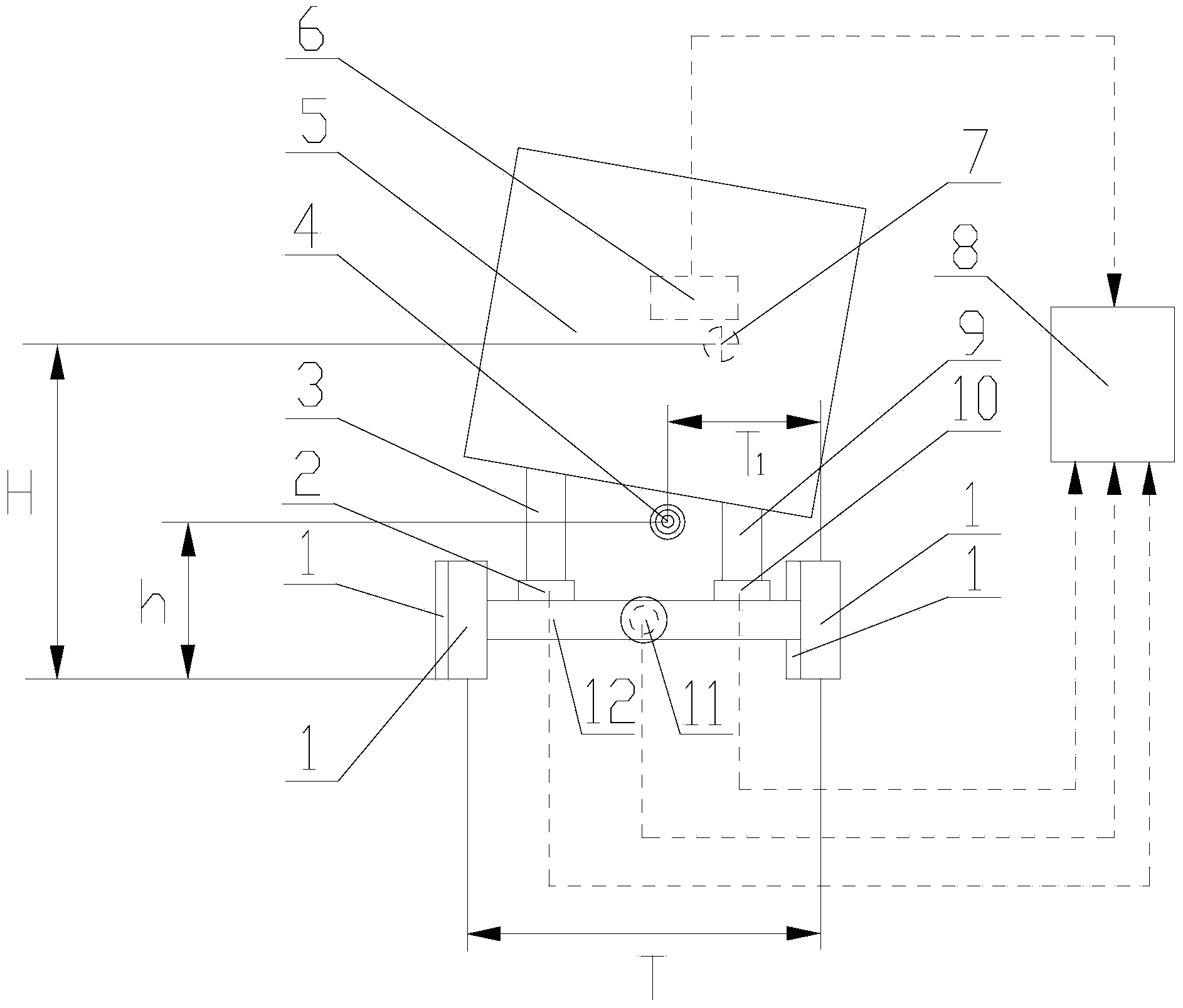
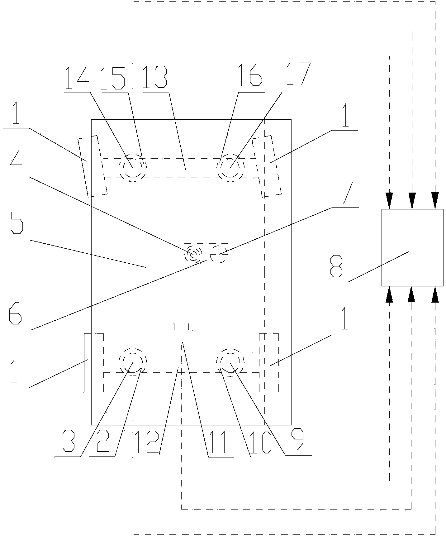
[0014] Such as figure 1 , figure 2 The vehicle roll center position measuring device shown includes a wheel 1, a left rear wheel vertical load sensor 2, a left rear suspension 3, a vehicle body 5, a center of mass sensing unit 6, a calculation unit 8, and a right rear suspension 9 , right rear wheel vertical load sensor 10, vehicle speed sensor 11, rear axle 12, front axle 13, left front suspension 14, left front wheel vertical load sensor 15, right front wheel vertical load sensor 16, right front suspension 17; The center of mass sensing unit 6 includes a lateral acceleration sensor, a yaw rate sensor and a roll angle sensor, and is fixedly installed on the vehicle body 5 at the center of mass of the vehicle; the two ends of the rear axle 12 and the front axle 13 are connected to the wheels 1; The upper end of the rear suspension 3 is fixedly connected with the vehicle body 5, and the lower end of the left rear suspension 3 is fixedly installed on the rear axle 12 thro...

Embodiment 2

[0016] This embodiment provides a method for calculating the center position of the vehicle roll. When the vehicle is in the process of rolling, the center of mass sensing unit 6 can measure the lateral acceleration, yaw rate, roll angular acceleration and roll angle at the center of mass of the vehicle. Vehicle speed sensor 11 can measure the running speed of automobile, and left rear wheel vertical load sensor 2, right rear wheel vertical load sensor 10, left front wheel vertical load sensor 15, right front wheel vertical load sensor 16 can measure the load that each wheel is subjected to. Vertical load, calculation unit 8 according to the formula Calculate the vertical distance h from the vehicle roll center to the center of mass, according to the formula Deduce the horizontal distance T from the center of the vehicle roll to the center of the right wheel 1 , where g is the acceleration of gravity, T is the horizontal distance between the wheels on both sides of the ...


PUM


Abstract

The invention relates to a vehicle roll center position measuring device. The invention provides the vehicle roll center position measuring device, aiming at the deficiencies in vehicle roll and rollover studies at present. The vehicle roll center position measuring device comprises a left rear wheel vertical load sensor, a left rear suspension, a centroid sensing unit, a calculating unit, a right rear suspension, a right rear wheel vertical load sensor, a vehicle speed sensor, a left front suspension, a left front wheel vertical load sensor, a right front wheel vertical load sensor, a right front suspension and the like. The invention also relates to a calculating method of a vehicle roll center position. With the adoption of the vehicle roll center position measuring device and the calculating method, as the positions of roll centers when a vehicle rolls and is in side tumbling can be calculated according to the vertical load of each wheel, the yaw angle speed of the vehicle, the roll angle of the vehicle and the running speed of the vehicle, the effects of the roll forecast and a roll prevention controlling system of the vehicle are effectively improved.

Description

technical field [0001] The invention relates to the technical field of vehicle roll and rollover research, in particular to a vehicle roll center position measuring device and a calculation method thereof. Background technique [0002] Vehicle roll stability is an important indicator to measure the safety performance of a vehicle. Large vehicle rolls or even rollovers may cause serious traffic accidents, which are second only to vehicle collisions. For a two-axis vehicle, the vehicle roll center refers to the intersection of the instantaneous axis around which the vehicle body rotates when the vehicle body rolls and the transverse vertical section where the vehicle's center of mass is located. Generally, the position of the vehicle's center of mass is used as the reference origin to indicate the vehicle's roll Central location. Many scholars and companies at home and abroad assume that the position of the center of vehicle roll remains unchanged when studying vehicle roll a...

Claims


Application Information

Patent Timeline
IPC IPC(8): B60W40/10B60W40/11
CPCB60W30/04B60W40/105B60W40/109B60W40/11B60W40/112B60W40/13B60W2520/10B60W2520/125B60W2520/18
Inventor 邱绪云高琦刘永辉曹凤萍李爱娟徐传燕王慧君李建英
Owner SHANDONG JIAOTONG UNIV
Learn More