Pattern sewing machine template device

A pattern machine and template technology, applied in the direction of pattern sewing machine, cloth feeding mechanism, sewing machine components, etc., can solve the problems of high economic cost, complex structure, troublesome assembly and debugging, etc., and achieve the improvement of work efficiency, the overall structure is simple, the configuration low cost effect

Inactive Publication Date: 2015-03-04
BULLMER ELECTROMECHANICAL TECH
View PDF6 Cites 10 Cited by
  • Summary
  • Abstract
  • Description
  • Claims
  • Application Information

AI Technical Summary

Problems solved by technology

The cylinder rod clamping device includes two clamping pins located at the rear end of the formwork. The clamping pins cooperate with the fasteners to fix the formwork and the base plate. This structure requires two clamping pins for each set of formwork , for users, a pattern machine often needs to be equipped with hundreds of templates, which requires twice the number of clamping pins as the number of templates, which makes the configuration cost of the template buckle device high for users. Both fasteners and fasteners are machined parts, which are easy to be lost during the assembly and disassembly of the template, and the replacement of the template is common. As a sewing user, they often do not have machining capabilities, which brings a lot of problems to subsequent use. inconvenient
In addition, the clamping device with rods on the cylinder has a complex structure and a large number of spare parts. Not only is the economic cost high, but also the assembly and debugging are troublesome, which makes the template replacement work cumbersome and affects the working efficiency of the pattern machine.

Method used


Image

  • Pattern sewing machine template device
  • Pattern sewing machine template device
  • Pattern sewing machine template device

Examples


Embodiment Construction

[0034] The implementation of the present invention will be illustrated by specific specific examples below, and those skilled in the art can easily understand other advantages and effects of the present invention from the contents disclosed in this specification.

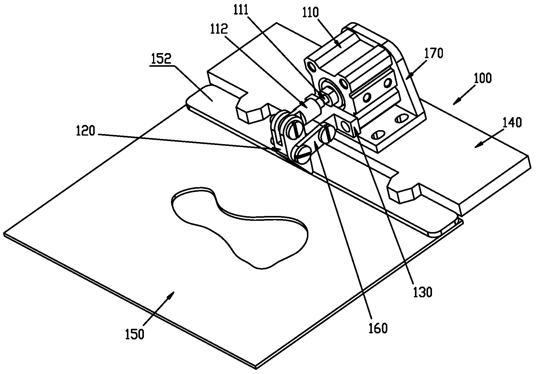
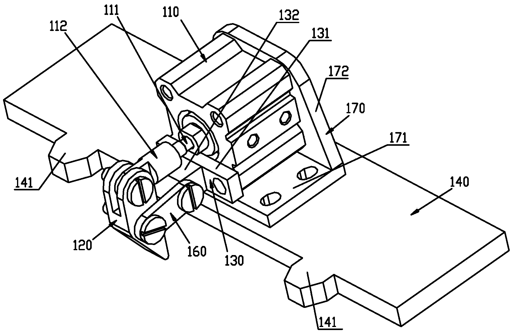
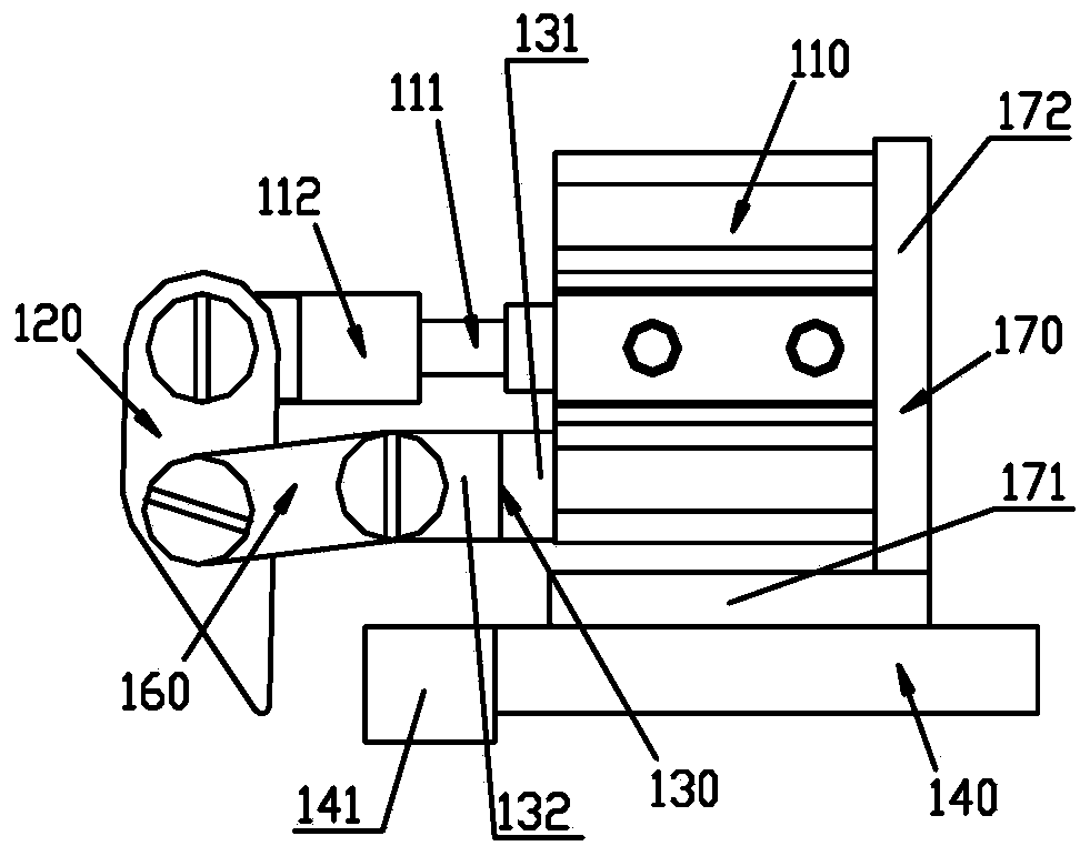
[0035] see Figure 1 to Figure 5 . It should be noted that the structures, proportions, sizes, etc. shown in the drawings attached to this specification are only used to match the content disclosed in the specification, for those who are familiar with this technology to understand and read, and are not used to limit the implementation of the present invention. Limiting conditions, so there is no technical substantive meaning, any modification of structure, change of proportional relationship or adjustment of size, without affecting the effect and purpose of the present invention, should still fall within the scope of the present invention. within the scope covered by the disclosed technical content. At the same ti...


PUM


Abstract

The invention provides a pattern sewing machine template device. The pattern sewing machine template device comprises a linear driver, a finger fastening piece, a bracket, a clamping seat and a template, wherein the rear end of the template and the front end of the clamping seat are mutually positioned in a manner of matching a positioning groove with a positioning lug boss; the rear end of the template is provided with a lug boss protruding out of the top surface of the template; the linear driver is fixed on the clamping seat; a retractable shaft of the linear driver is movably connected with the upper end of the finger fastening piece; the middle part of the finger fastening piece is movably connected with the bracket and the lower end of the finger fastening piece extends to the upper side of the template; the bracket is fixedly mounted relative to the clamping seat; when the retractable shaft of the linear driver is at a stretching-out state, the lower end of the finger fastening piece swings backwards and tightly presses the lug boss. According to the pattern sewing machine template device, the template is clamped and loosened by the stretching-out and retraction of the retractable shaft of the linear driver so that the template is convenient and rapid to detach and the working efficiency of a pattern sewing machine is improved; the whole structure is simple so that the configuration cost is also low.

Description

technical field [0001] The invention relates to the technical field of sewing equipment, in particular to a pattern machine template device. Background technique [0002] Pattern machine is an important sewing equipment, which is widely used in the sewing of various handbags, garments, textiles, leather goods, bags, shoes, belts, sports equipment, etc. For different patterns, only need to change the template, And correspondingly adjust the feeding program of the template to complete the sewing of various patterns. [0003] The templates in the prior art are fixed to the base plate of the template feeding system through a cylinder rod clamping device. The cylinder rod clamping device includes two clamping pins located at the rear end of the formwork. The clamping pins cooperate with the fasteners to fix the formwork and the base plate. This structure requires two clamping pins for each set of formwork , for users, a pattern machine often needs to be equipped with hundreds o...

Claims


Application Information

Patent Timeline
Patent Type & Authority Applications(China)
IPC IPC(8): D05B9/00D05B35/00
CPCD05B39/00
Inventor 王俊跃
Owner BULLMER ELECTROMECHANICAL TECH
Why Eureka
Try Eureka