Vehicle synchronizer

A synchronizer and automobile technology, applied in the direction of clutches, mechanically driven clutches, mechanical equipment, etc., can solve the problems of poor gear selection comfort, shift shock and fatigue, poor manufacturing consistency, etc., to achieve small shift resistance, shift The effect of good file curve and simple assembly

Inactive Publication Date: 2015-03-04
ANHUI XINGRUI GEAR TRANSMISSION
View PDF9 Cites 2 Cited by
  • Summary
  • Abstract
  • Description
  • Claims
  • Application Information

AI Technical Summary

Problems solved by technology

[0004] In order to make the driver perceive the shifting force and stroke of the manual mechanical shifting automobile transmission, the current common practice in the design of the synchronizer structure is: the shape of the inner slider groove of the tooth sleeve, the synchronizer sliding Block structure, "C" spring stiffness, design and coordination of synchronous ring and gear teeth, the defect of this design method is: the shape design of the gear sleeve slider groove matches the stroke of the shift mechanism, and the "C" spring The manufacturing consistency is poor, and when the parts of the shift mechanism are in a downward trend, the matching synchronizer unit is in the stage of dialing the ring, the comfort of gear selection becomes poor, and it is easy to produce a large perceived shift force; It does not match the actual needs of the transmission; in the process of the end of the synchronization of the transmission shift synchronizer and the tooth sleeve entering the engaging teeth, the driver still relies on the driver's forced push to shift the gear, which cannot generate self-suction force, and is prone to shift shock and fatigue

Method used


Image

  • Vehicle synchronizer
  • Vehicle synchronizer

Examples


Embodiment Construction

[0020] In order to make it easy to understand the technical means, creative features, work flow, and use methods of the present invention to achieve the objectives and effects, the technical solutions in the embodiments of the present invention will be clearly and completely described below in conjunction with the embodiments of the present invention. Obviously, The described embodiments are only a part of the embodiments of the present invention, rather than all the embodiments. Based on the embodiments of the present invention, all other embodiments obtained by those of ordinary skill in the art without creative work shall fall within the protection scope of the present invention.

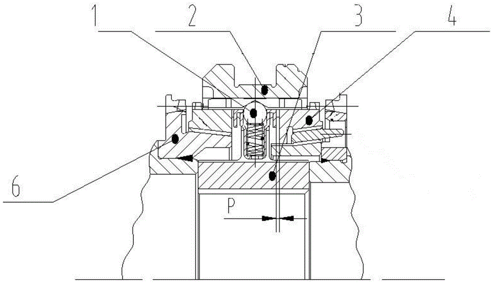
[0021] Such as figure 1 As shown, an automobile synchronizer includes: a slider 1, a gear sleeve 2, a gear hub 3, a synchronizing ring 4, and a gear engaging tooth 6. The gear engaging tooth 6 is mounted on the gear hub 3, and the gear engaging tooth 6 There is a synchronization ring 4, the upper pa...


PUM


Abstract

The invention provides a vehicle synchronizer. The vehicle synchronizer comprises a slider, a gear sleeve, a gear hub, a synchronous ring and a gear soldered tooth, wherein the gear soldered tooth is arranged on the gear hub; the synchronous ring is arranged in the gear soldered tooth; the gear sleeve is arranged on the upper part of the synchronous ring; the slider is arranged between the gear sleeve and the synchronous ring; the slider consists of a spring, a steel ball and a drawn cup; the steel ball is in contact with a slider groove below the gear sleeve; the drawn cup is in contact with the gear hub; the slider is arranged between the gear sleeve and the gear hub. A gap between the synchronizer slider and the synchronous ring and a gap between the gear sleeve and the synchronous ring are in fit connection, the gear shifting handiness is perceived in the gear shifting process under the action of the synchronizer slider, and a driver clearly perceives the gear shifting smoothness, namely the gear shifting comfort is good; meanwhile, a gear shifting curve is good during objective evaluation.

Description

technical field [0001] The invention relates to the technical field of automobile synchronizers, in particular to an automobile synchronizer. Background technique [0002] As the car enters the family field, the competition in the car market is becoming increasingly fierce, and customers have higher and higher requirements for car handling performance. Automakers have had to work on improving the shifting quality of their cars. The shifting quality of the manual mechanical shifting automobile transmission directly affects the shifting performance of the vehicle, and the contribution of the synchronizer unit to the shifting quality is particularly important. [0003] The design of the synchronizer unit determines the design of the vehicle's shifting stroke and the comfort of shifting. In the subjective and objective evaluation of the shifting quality of manual mechanical shifting automobile transmissions, the evaluators have requirements for shifting comfort. According to ...

Claims


Application Information

Patent Timeline
Patent Type & Authority Applications(China)
IPC IPC(8): F16D23/02
Inventor 张敏时永尹夕兵
Owner ANHUI XINGRUI GEAR TRANSMISSION
Why Eureka
Try Eureka