
High-pressure and high-thrust two-position three-way ball valve structure

A two-position, three-way, high-thrust technology, used in multi-way valves, valve details, valve devices, etc., can solve the problems of inability to take into account high-frequency response and large flow, and it is difficult to keep the ball valve seat still.

Inactive Publication Date: 2017-07-21
ZHEJIANG UNIV
View PDF11 Cites 0 Cited by
  • Summary
  • Abstract
  • Description
  • Claims
  • Application Information

AI Technical Summary

Problems solved by technology

[0005] In order to overcome the shortcomings of the existing high-speed switching valves that it is difficult to keep the ball valve seat still and cannot take into account high-frequency response and large flow under the condition of high oil pressure and large thrust, the present invention provides an effective valve under high oil pressure and large thrust. Keep the ball valve seat still, high-pressure and high-thrust two-position three-way ball valve structure with high frequency response and large flow

Method used


Image

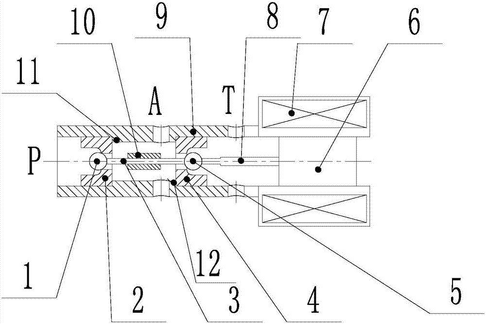
  • High-pressure and high-thrust two-position three-way ball valve structure
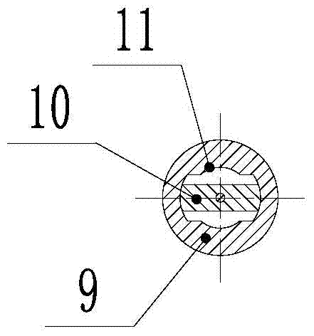
  • High-pressure and high-thrust two-position three-way ball valve structure

Examples


Embodiment Construction

[0019] The present invention will be further described below in conjunction with the accompanying drawings.

[0020] refer to figure 1 with figure 2 , a high-pressure and high-thrust two-position three-way ball valve structure, including a valve sleeve 9, a left steel ball seat 2, a push pin seat 10, a right steel ball seat 4 and an armature 6 are arranged inside the valve sleeve 9, and the outer side of the armature 6 Arrange the electromagnetic coil 7 for controlling the action of the armature, the armature 6 is connected with the push rod 8, the end of the push rod 8 is connected with the right end of the right steel ball 5, and the right steel ball 5 is located on the right steel ball seat 4 In the through hole, the 5 left ends of the right steel ball are connected with the right end of the push pin 3, the push pin 3 is installed on the push pin seat 10, the left end of the push pin 3 is connected with the left steel ball 1, and the left steel ball 1 Located in the left...


PUM


Abstract

The invention discloses a high-pressure big-thrust two-position three-way ball valve structure, which comprises a valve bush, wherein a left steel ball seat, a pushing pin seat, a right steel ball seat and an armature are arranged in the valve bush; the outer side of the armature is provided with a solenoid coil used for controlling the action of the armature; the armature is connected with a mandril; the end part of the mandril is connected with the right end of a right steel ball; the right steel ball is positioned in a through hole of the right steel ball seat; the left end of the right steel ball is connected with the right end of a pushing pin; the pushing pin is installed on the pushing pin seat; the left end of the pushing pin is connected with a left steel ball; the left steel ball is positioned in the left steel ball seat; the inner cavity of the valve bush is provided with a left boss and a right boss; the left steel ball seat is positioned in the left boss, and the left steel ball and the left boss are in mutual large interference fit; the right steel ball is positioned in the right boss, and the right steel ball and the right boss are in mutual large interference fit. The invention provides the high-oil-pressure big-thrust two-position three-way ball valve structure which can effectively keep a ball valve set stationary and also has high frequency response and large flow under the conditions of high oil pressure and big thrust.

Description

technical field [0001] The invention relates to a ball valve structure. Background technique [0002] At present, high-speed switching valves are playing an increasingly important role in the hydraulic field, such as fuel injection systems, ABS anti-lock braking systems, etc. Most of the two-position three-way solenoid valves in the market that can realize the switching function are spring-returning spool valve structures. Due to the existence of springs, the valve body structure and processing technology of this structure are relatively complicated. In addition, it is necessary to overcome the spring force, so there is a higher requirement for the magnitude of the electromagnetic force. [0003] As a commonly used structure in the hydraulic field, the ball valve structure is mostly used in one-way valves, and has better sealing performance, that is, the action of a single steel ball. There are few structures in the market where two steel balls work together, because the s...

Claims


Application Information

Patent Timeline
Patent Type & Authority Patents(China)
IPC IPC(8): F16K11/056F16K31/06
CPCF16K11/056F16K31/06
Inventor 张斌钟麒马吉恩杨华勇
Owner ZHEJIANG UNIV
Learn More