

Sawtooth porous type plate-fin heat exchanger
A zigzag, perforated plate technology, used in heat exchange equipment, lighting and heating equipment, laminated components, etc., can solve problems such as low heat transfer efficiency, improve heat transfer efficiency, strengthen heat transfer effect, and compact structure. Effect
Inactive Publication Date: 2015-03-04
中国船舶重工集团公司第七〇三研究所
View PDF4 Cites 4 Cited by
- Summary
- Abstract
- Description
- Claims
- Application Information
AI Technical Summary
Problems solved by technology
In a normal design, the heat transfer area of the heat transfer fins is about 67% to 88% of the total heat transfer area of the heat exchanger, and the connection between the heat transfer fins and the separator is perfect brazing, so most of the heat transfer The heat transfer fins pass through the heat transfer fins and pass to the cold fluid from the partition. Since the heat transfer of the heat transfer fins is not as direct as the partition, the heat transfer fins have a "secondary surface" It is said that the heat transfer efficiency of the secondary heat transfer surface is generally lower than that of the primary heat transfer surface.
Method used
View moreImage
Smart ImageViewing Examples

Examples
Embodiment Construction
Login to View More PUM
 Abstract
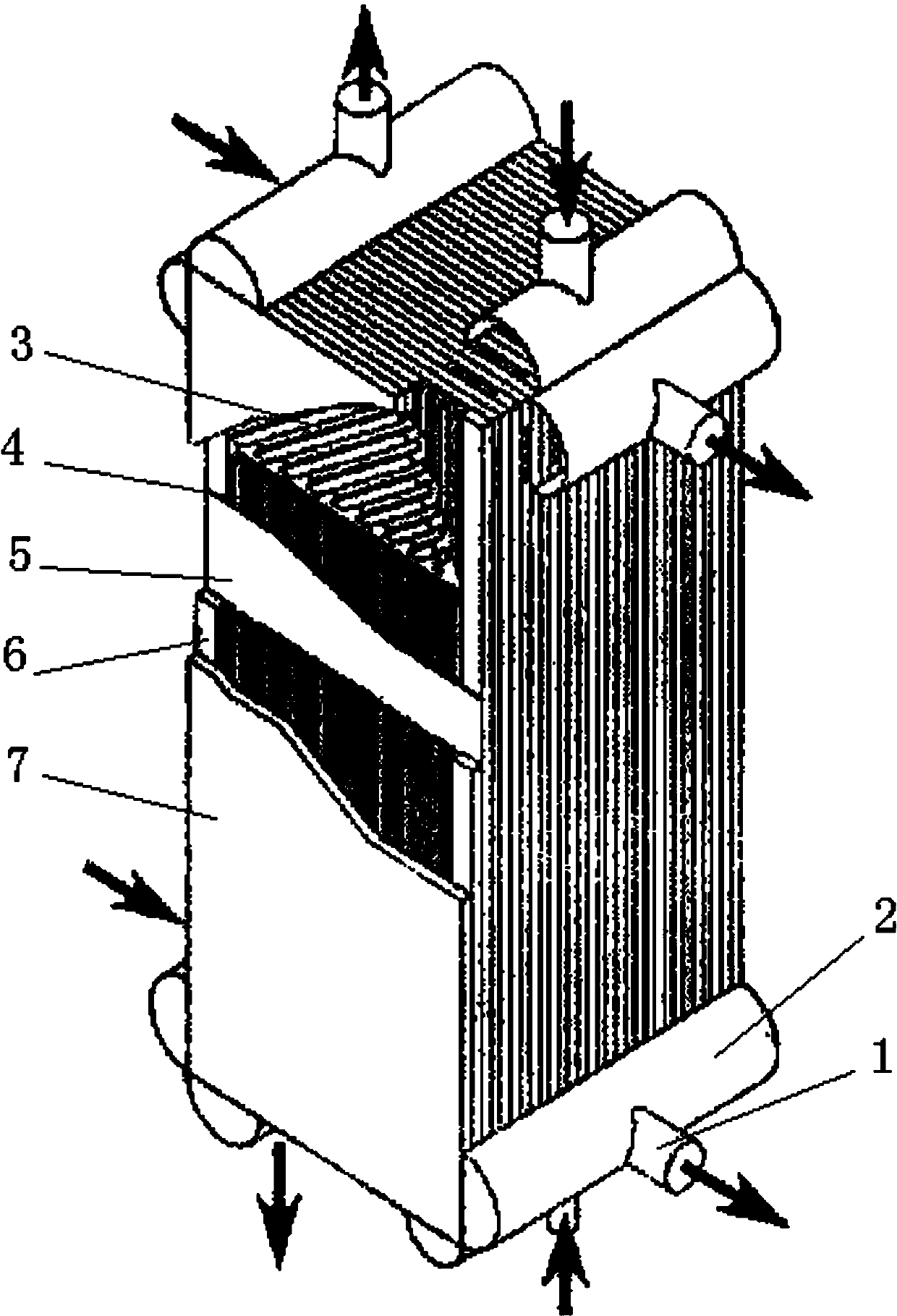
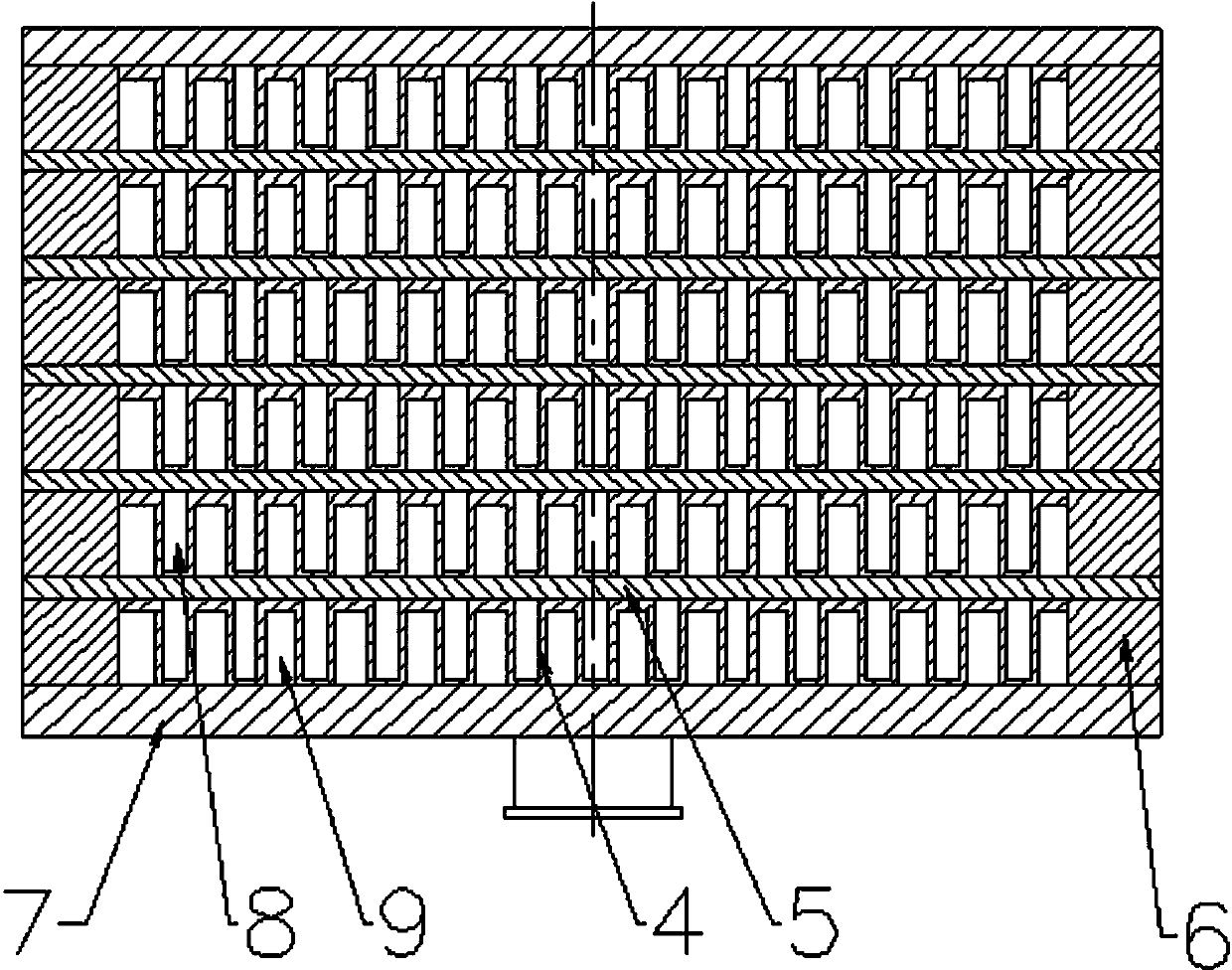
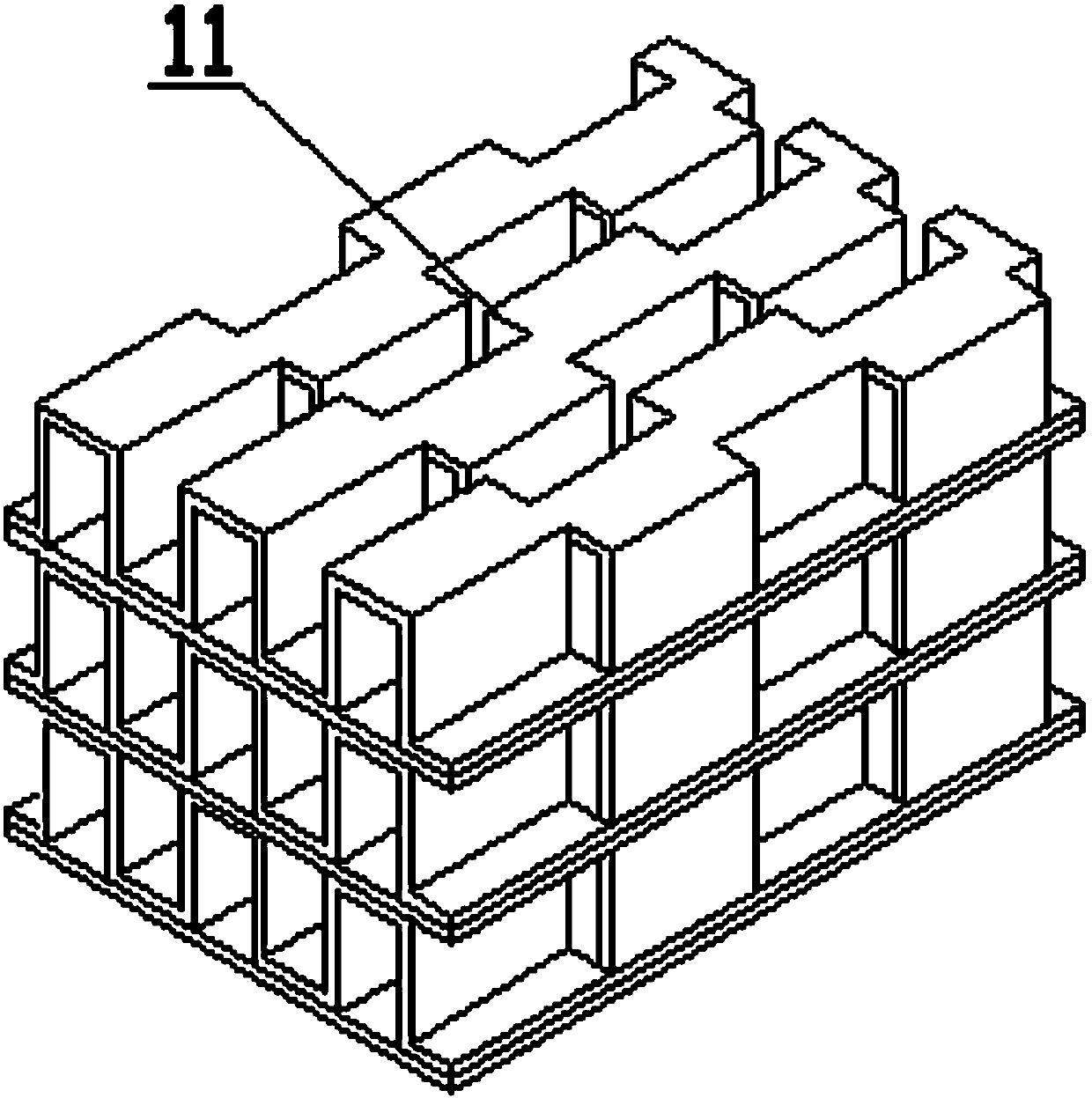
The invention provides a sawtooth porous type plate-fin heat exchanger. The existing plate-fin heat exchanger is formed by heat exchange fins, a baffle, a seal strip, a flow deflector, an end plate, an end socket, a liquid inlet and outlet connection pipe and the like. Under the condition that the existing structure is not changed, the characteristics of porous fins and sawtooth fins are combined, many short fragments are cut in the teeth length direction of the porous fin, and sawtooth shapes are staggered at intervals in the teeth length direction of the porous fin to obtain the sawtooth porous type fins. When heat exchange fluid flows in a runner, the sawtooth facilitates fluid disturbance, the heat exchange function is strengthened, and the heat exchange efficiency of the heat exchange fin is improved. By adopting the technical scheme, the plate-fin heat exchanger is formed by porous sawtooth fins; the heat exchange effect is strengthened; the heat exchange efficiency of the heat exchange fin is improved, and the structure of the plate-fin heat exchanger is more compact.
Description
Technical field: The invention relates to the technical field of heat exchangers, in particular to a zigzag porous plate-fin heat exchanger. Background technique: With the development of modern science and technology, heat exchangers are needed from the petrochemical industry to the space industry. Due to the wide variety of heat exchangers, they can be classified into tube type, plate type and other types according to the shape and structure of their heat transfer surfaces. Type heat exchanger. The tube heat exchanger can be divided into coil heat exchanger, casing heat exchanger, shell and tube type; plate heat exchanger can be divided into spiral plate heat exchanger, plate heat exchanger, plate and shell heat exchanger Heaters and plate-fin heat exchangers. Plate-fin heat exchanger is a heat exchange equipment with outstanding advantages such as compact structure, light weight, high heat transfer efficiency and good economy. It is used in aerospace, refrigeration and a...
Claims
Login to View More Application Information
Patent Timeline
 Patent Type & Authority Applications(China)
IPC IPC(8): F28F3/02
Inventor 刘伟李东明张立超张晓云
Owner 中国船舶重工集团公司第七〇三研究所