
Flow error correction method for time difference type ultrasonic heat meter

An error correction and ultrasonic technology, applied in the field of time difference ultrasonic heat meter flow error correction, can solve the problems of inability to guarantee errors, low production efficiency, and inability to guarantee the accuracy of flow measurement errors, so as to improve production efficiency and ensure The effect of accuracy

Active Publication Date: 2015-03-04
HUNAN WEIMING ENERGY TECH CO LTD
View PDF4 Cites 14 Cited by
  • Summary
  • Abstract
  • Description
  • Claims
  • Application Information

AI Technical Summary

Problems solved by technology

However, due to the nonlinear distribution of the flow correction compensation coefficient in the full-scale flow range, if you want to ensure the accuracy of the flow error within the full-scale flow range, you need to calibrate many flow points to obtain a more accurate correction compensation curve , but this method will lead to very low production efficiency due to the large number of flow points to be calibrated and corrected during production
Therefore, in order to improve production efficiency, most manufacturers reduce the calibration of flow points in the actual production process, resulting in a large difference between the corrected compensation curve and the actual situation, and cannot guarantee the accuracy of the flow measurement error within the flow range of the full range. At the same time, due to the wide range of water temperature required by the heat meter, the error of the same flow point is different under different water temperatures. Inaccurate flow measurement error at different water temperatures

Method used


Image

  • Flow error correction method for time difference type ultrasonic heat meter
  • Flow error correction method for time difference type ultrasonic heat meter
  • Flow error correction method for time difference type ultrasonic heat meter

Examples


Embodiment Construction

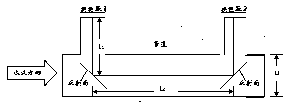
[0029] Such as figure 1 As shown, the present invention is mainly suitable for the flow measurement of the transit-time ultrasonic heat meter. The flow measurement of the transit-time ultrasonic heat meter refers to the application of a pair of ultrasonic transducers to send and receive ultrasonic waves alternately (or simultaneously), and to indirectly measure the flow velocity of the fluid by observing the time difference between the downstream and countercurrent propagation of the ultrasonic waves in the medium, and then pass the flow velocity to calculate flow.

[0030] The transit-time flow measurement method first obtains the relevant time data according to the following formula.

[0031] T 1 = 2 L 1 C + L 2 C + V ...


PUM


Abstract

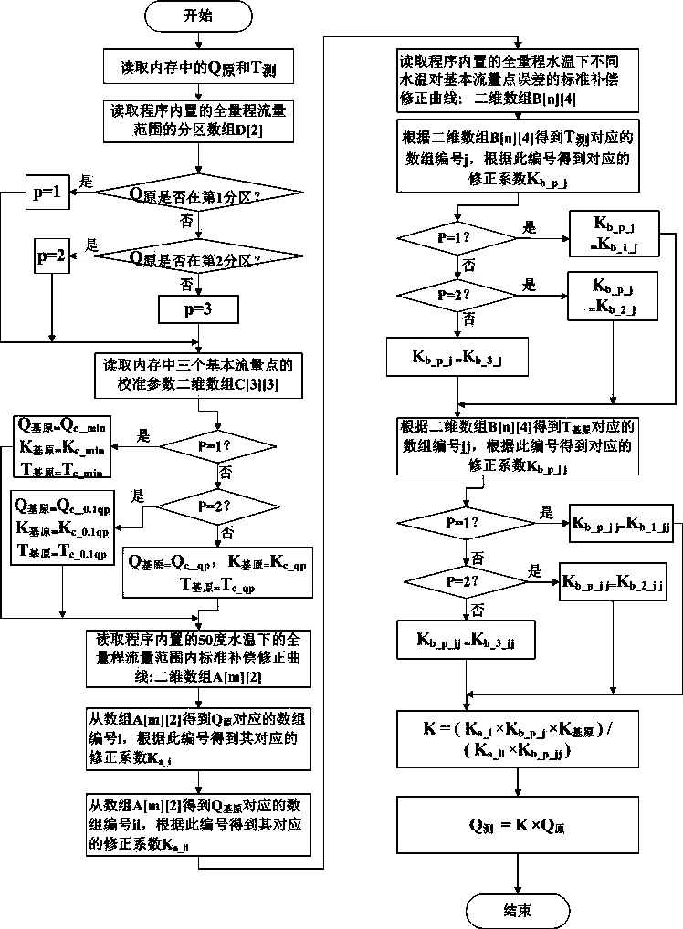
The invention discloses a flow error correction method for a time difference type ultrasonic heat meter. The flow error correction method comprises the steps of selecting three basic flow points which are respectively distributed in three regions within a full-measuring-range flow range, and setting a standard compensation correction curve within the full-measuring-range flow range under the water temperature being M DEG C and a standard compensation correction curve of different water temperatures under the full-measuring-range water temperature on the errors of the basic flow points; performing calibration correction on the flow points under the water temperature being M DEG C, and saving a non-corrected flow value, an error correction compensation coefficient and the water temperature during calibration; correcting the compensation coefficient and the water temperature according to the errors of the basic flow points during calibration, and upwards or downwards moving the two standard compensation correction curves in a subsection manner according to the region to obtain real compensation correction curves of the ultrasonic heat meter; obtaining a real error correction compensation coefficient according to the two real compensation correction curves. According to the flow error correction method, the accuracy of the full-measuring-range water temperature and the flow error within the full-measuring-range flow range can be guaranteed, and the production efficiency is improved.

Description

technical field [0001] The invention relates to a flow error correction method of a transit-time ultrasonic heat meter. Background technique [0002] Time-of-flight ultrasonic flow measurement is a common method for ultrasonic heat meters to measure flow. Its principle is to use a pair of ultrasonic transducers to alternately (or simultaneously) send and receive ultrasonic waves, and to observe the time difference between forward and reverse flow of ultrasonic waves in the medium. It is an indirect measurement method to measure the flow velocity of the fluid and then calculate the flow rate through the flow velocity. However, in practical applications, the flow rate is affected by different factors, such as: the length of the sound channel, the installation angle of the ultrasonic transducer, and the measurement accuracy of the pipe radius. Signal distortion or loss, the measurement accuracy of ultrasonic time difference, the temperature change of the measured liquid, etc., ...

Claims


Application Information

Patent Timeline
IPC IPC(8): G01F25/00
Inventor 张慧娟赵永球
Owner HUNAN WEIMING ENERGY TECH CO LTD
Learn More