
No-blind zone precise locating system and locating method for radio frequency identification

A radio frequency identification and precise positioning technology, applied in the field of radio frequency identification precise positioning system, can solve the problems of inaccurate positioning, long positioning time, poor positioning accuracy, etc., and achieve the effect of precise positioning

Active Publication Date: 2015-03-04
XIAMEN ANFUDI INFORMATION TECH
View PDF4 Cites 13 Cited by
  • Summary
  • Abstract
  • Description
  • Claims
  • Application Information

AI Technical Summary

Problems solved by technology

[0002] Active RIFD technology has been widely used in indoor rough positioning of people and objects. However, general active RFID positioning systems have disadvantages such as long positioning time, inaccurate positioning, and poor positioning accuracy (usually tens of meters).
For high-precision positioning and short-distance entry and exit positioning, existing active RFID technology has been difficult to meet the requirements. The distance and tunnel simultaneously generate the demand for signal synchronization; in order to meet the demand for high-precision positioning and short-distance in-and-out positioning, and improve the positioning accuracy of active RFID, this case arises from this

Method used


Image

  • No-blind zone precise locating system and locating method for radio frequency identification
  • No-blind zone precise locating system and locating method for radio frequency identification
  • No-blind zone precise locating system and locating method for radio frequency identification

Examples


Embodiment Construction

[0030] The present invention will be described in detail below in conjunction with the accompanying drawings and specific embodiments.

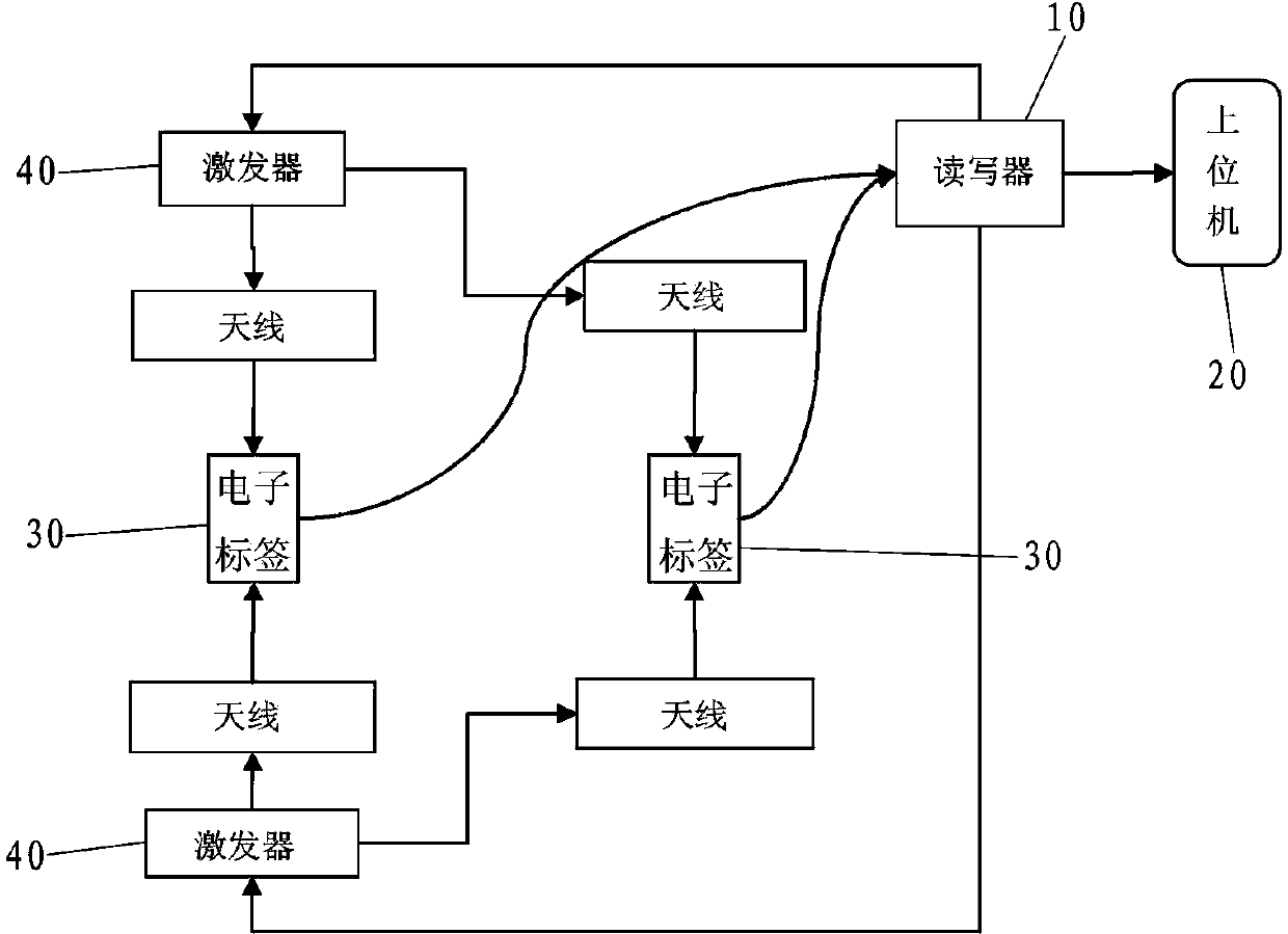
[0031] refer to Figure 1 to Figure 6 As shown, a radio frequency identification precise positioning system without blind spots disclosed by the present invention includes a reader 10 , a host computer 20 , an electronic tag 30 and an exciter 40 .

[0032] like figure 1 As shown, the reader 10 is connected to the upper computer 20 by wire, the reader 10 communicates with the exciter 40 through an ultra-high frequency wireless synchronization signal, and the exciter 40 communicates with the electronic tag 30 through a low-frequency wireless excitation signal. The electronic tag 30 It is connected with the reader-writer 10 through a UHF wireless signal.

[0033] like figure 2 As shown, the exciter 40 includes a UHF wireless signal receiving module 401, an UHF antenna 402, a low frequency excitation module 403, a low frequency antenna 404 an...


PUM


Abstract

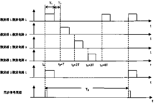
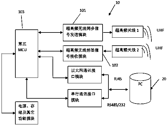
The invention discloses a no-blind zone precise locating system and locating method for radio frequency identification. A low-frequency excitation module of a laser comprises at least two excitation circuits with staggered operation time sequences and different numbers, and the different excitation circuits form a low-frequency excitation signal intersection zone; a low-frequency receiving module gathers low-frequency excitation signals and sends mark information to a reader-writer through an ultrahigh frequency wireless sending module; an ultrahigh frequency wireless label signal receiving module receives label signals through an ultrahigh frequency antenna and transmits the label information and low-frequency excitation mark information to an upper computer; an ultrahigh frequency wireless synchronization signal sending module transmits synchronization signals to a first MCU in a wireless mode to control the synchronization state of the operation time sequences of the low-frequency excitation circuits. The no-blind zone precise locating system and locating method for the radio frequency identification realize the no-blind zone precise locating for management targets through using ultrahigh frequency wireless signals to synchronize low-frequency trigger signal time sequences.

Description

technical field [0001] The invention relates to a radio frequency identification precise positioning system and a positioning method without blind areas. Background technique [0002] Active RIFD technology has been widely used in indoor rough positioning of people and objects. However, general active RFID positioning systems have disadvantages such as long positioning time, inaccurate positioning, and poor positioning accuracy (generally tens of meters). For high-precision positioning and short-distance entry and exit positioning, existing active RFID technology has been difficult to meet the requirements. The distance and tunnel simultaneously generate the demand for signal synchronization; in order to meet the demand for high-precision positioning and short-distance entry and exit positioning, and improve the positioning accuracy of active RFID, this case was born. Contents of the invention [0003] The purpose of the present invention is to provide a radio frequency i...

Claims


Application Information

Patent Timeline
IPC IPC(8): G06K17/00
Inventor 董放人陈财林满照
Owner XIAMEN ANFUDI INFORMATION TECH
Learn More