
A Pneumatic Tripping Structure of Grounding Wire Operating Rod

A technology of operating rods and grounding wires, which is applied in the field of power transformation and inspection equipment, can solve the problems that grounding equipment is not suitable for separating grounding wires and operating rods, troublesome detachment process, oil leakage, air leakage, etc., so as to avoid force and pneumatic The mechanism is simple and the effect of reducing equipment damage

Active Publication Date: 2016-10-05
STATE GRID CORP OF CHINA +2
View PDF6 Cites 0 Cited by
  • Summary
  • Abstract
  • Description
  • Claims
  • Application Information

AI Technical Summary

Problems solved by technology

Due to the diversity of grounding equipment, such as wires, which are soft and unable to withstand large forces, the detachment process is more troublesome; such as high-voltage bushings, if the detachment force is large, it is easy to cause equipment damage, oil leakage, air leakage, etc.
Therefore, the grounding equipment should not be used as a stress point for separating the grounding wire and the operating rod.

Method used


Image

  • A Pneumatic Tripping Structure of Grounding Wire Operating Rod
  • A Pneumatic Tripping Structure of Grounding Wire Operating Rod
  • A Pneumatic Tripping Structure of Grounding Wire Operating Rod

Examples


Embodiment Construction

[0010] The present invention will be further described below with reference to the accompanying drawings and embodiments. While the invention will be described in conjunction with the preferred embodiments, it will be understood that it is not intended to limit the invention to the described embodiments. On the contrary, the invention is to cover alternatives, modifications and equivalents, which may be included within the scope of the invention as defined by the appended claims.

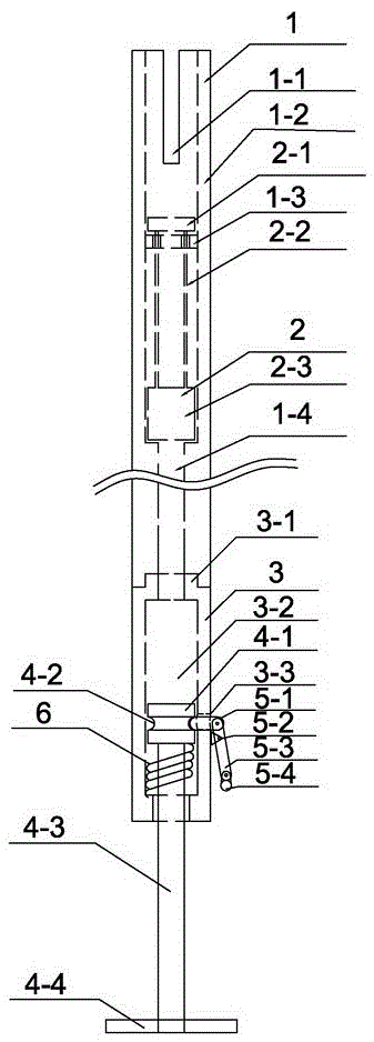
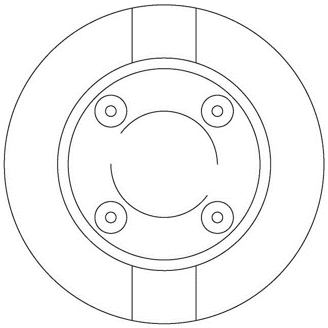
[0011] refer to Figure 1 to Figure 7 As shown, in the pneumatic release structure of the grounding wire operating rod in this embodiment, the upper end body 1 of the grounding wire operating rod is equipped with a push rod piston 2, and the pneumatic operating end of the grounding wire is composed of the operating end body 3, the piston 4, the detent 5 and the The energy storage spring 6 is composed of four parts; the body 1 is composed of a grounding wire terminal card slot 1-1, an outer wall 1-2...


PUM


Abstract

The invention discloses a ground wire operation rod pneumatic tripping structure comprising a ground wire operation rod upper end head body, a push rod piston, an operation end body, a piston, a pawl and an energy storage spring. The body is composed of a ground wire end head clamping groove, an external wall, a strong permanent magnet and an air channel. The push rod piston is composed of a push plate, a connecting rod and the piston. The operation end body is composed of an operation end interface, an operation end air chamber and a pawl groove. The piston is composed of a piston body, a pawl limiting groove, a piston connecting rod and an energy storage handle. The pawl is composed of a pawl head, a pawl top point, an operation rod and an anti-error lock. The energy storage spring is composed of the energy storage spring. The beneficial effects of the ground wire operation rod pneumatic tripping structure are that the compressed air acts as power to separate the operation rod and the end head in the operation rod upper end head so that force bearing of ground equipment can be avoided and thus equipment damage is reduced. Meanwhile, the adopted pneumatic structure is simple and easy to maintain, and force output can be performed via adjusting the size of the spring according to requirements so that pneumatic requirements of most industries can be met.

Description

technical field [0001] The invention relates to an automatic device for automatic tripping between the grounding wire and the operating rod, especially a self-contained simple compressed air generating device, which uses compressed air as the structure of the operating rod for the grounding wire that is separated from the power, and belongs to the substation inspection equipment technology field. Background technique [0002] In the existing method, when the operating rod and the grounding wire are separated, the grounding equipment is used as the side that bears the force. Due to the diversity of grounding equipment, such as wires, which are soft and unable to withstand large forces, the detachment process is more troublesome; such as high-voltage bushings, if the detachment force is large, it is easy to cause equipment damage, oil leakage, air leakage, etc. Therefore, the grounding equipment should not be used as a stress point for separating the grounding wire and the ...

Claims


Application Information

Patent Timeline
Patent Type & Authority Patents(China)
IPC IPC(8): H01R43/00
CPCH01R43/00
Inventor 杨继崇贾海源陈朝晖张华杜洪亮孙侃曹康高唯晶
Owner STATE GRID CORP OF CHINA
Learn More