

Elevator device
A technology of elevators and stopping devices, which is applied in the direction of transportation, packaging, elevators, etc., which can solve the problems that the car cannot fall and stop, and achieve the effect of shortening the journey
- Summary
- Abstract
- Description
- Claims
- Application Information
AI Technical Summary
Problems solved by technology
Method used
Image

Examples
Embodiment approach 1
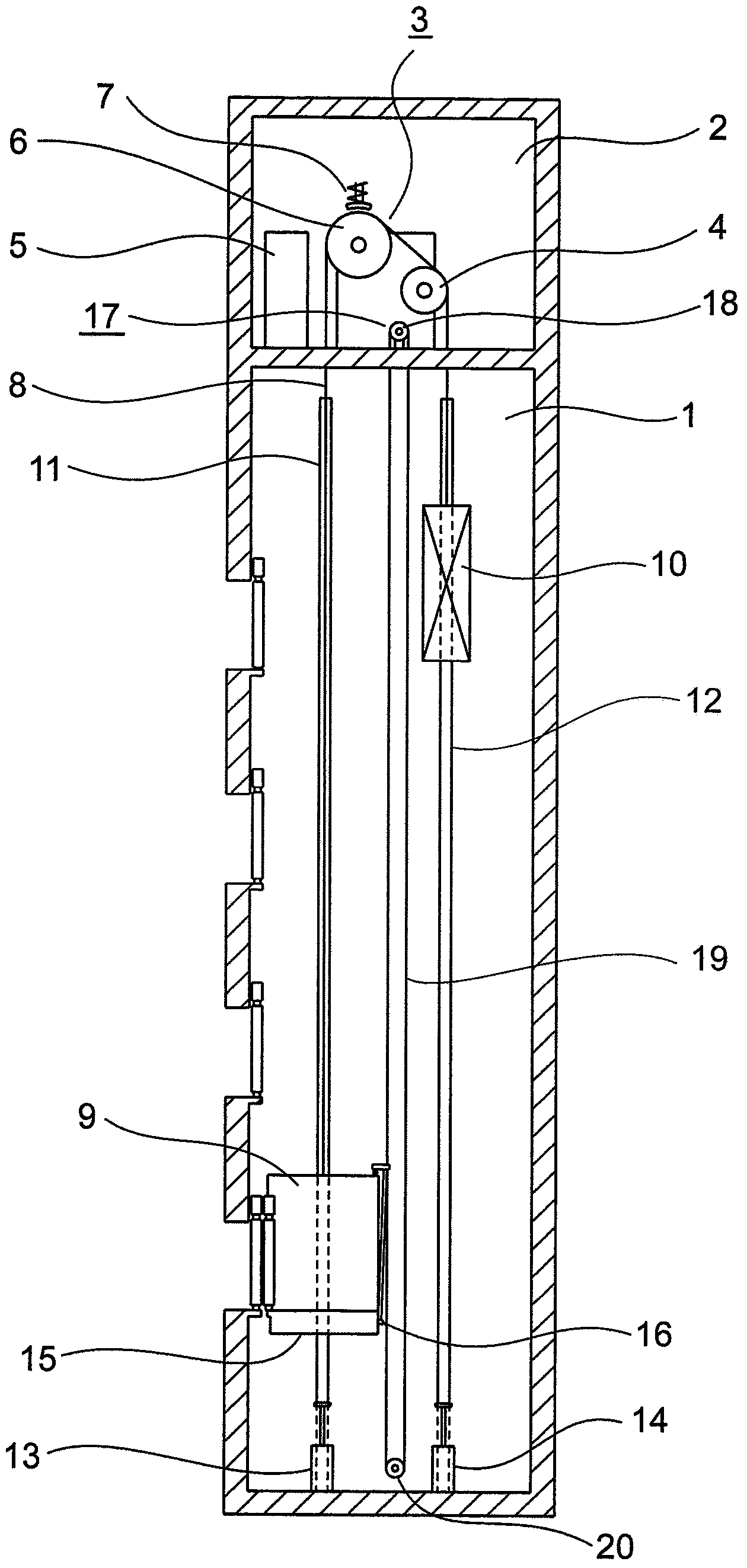
[0032] figure 1 It is a configuration diagram showing the elevator apparatus according to Embodiment 1 of the present invention. In the figure, a machine room 2 is provided on the upper part of the hoistway 1 . The machine room 2 is provided with a traction machine (drive device) 3 , a deflector pulley 4 and a control device 5 . The hoisting machine 3 has a driving sheave 6 , a hoisting machine motor that rotates the driving sheave 6 , and a hoisting machine brake (electromagnetic brake) 7 that brakes the rotation of the driving sheave 6 .
[0033] The traction machine brake 7 has: a brake wheel (brake drum or brake disc), which is coaxially engaged with the drive sheave 6; a brake shoe, which contacts / separates from the brake wheel; a brake spring, which will brake The moving shoe pushes against the brake wheel to apply a braking force; and the electromagnet overcomes the force of the brake spring to make the brake shoe leave the brake wheel to release the braking force.
...
Embodiment approach 2
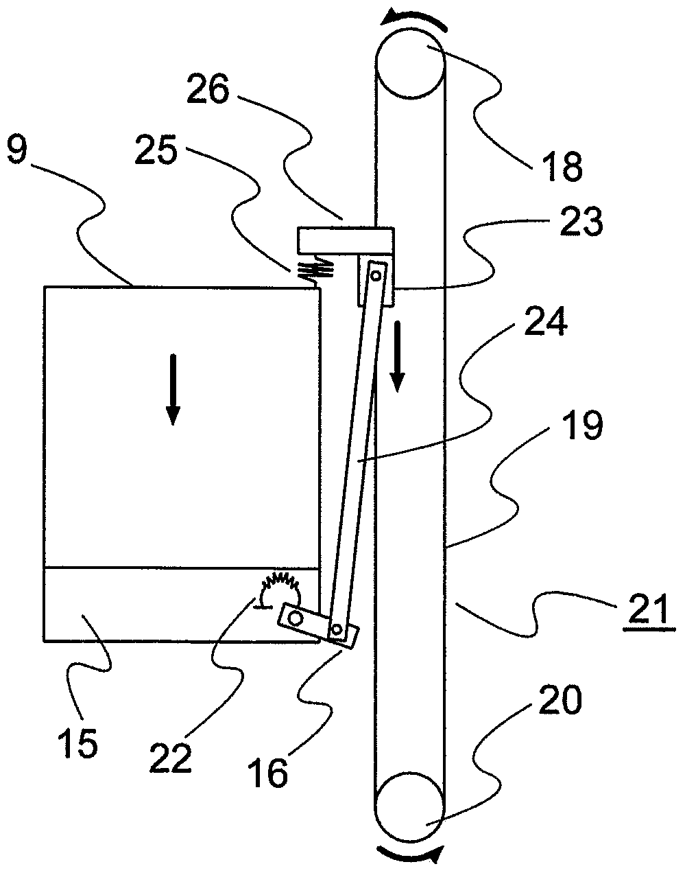
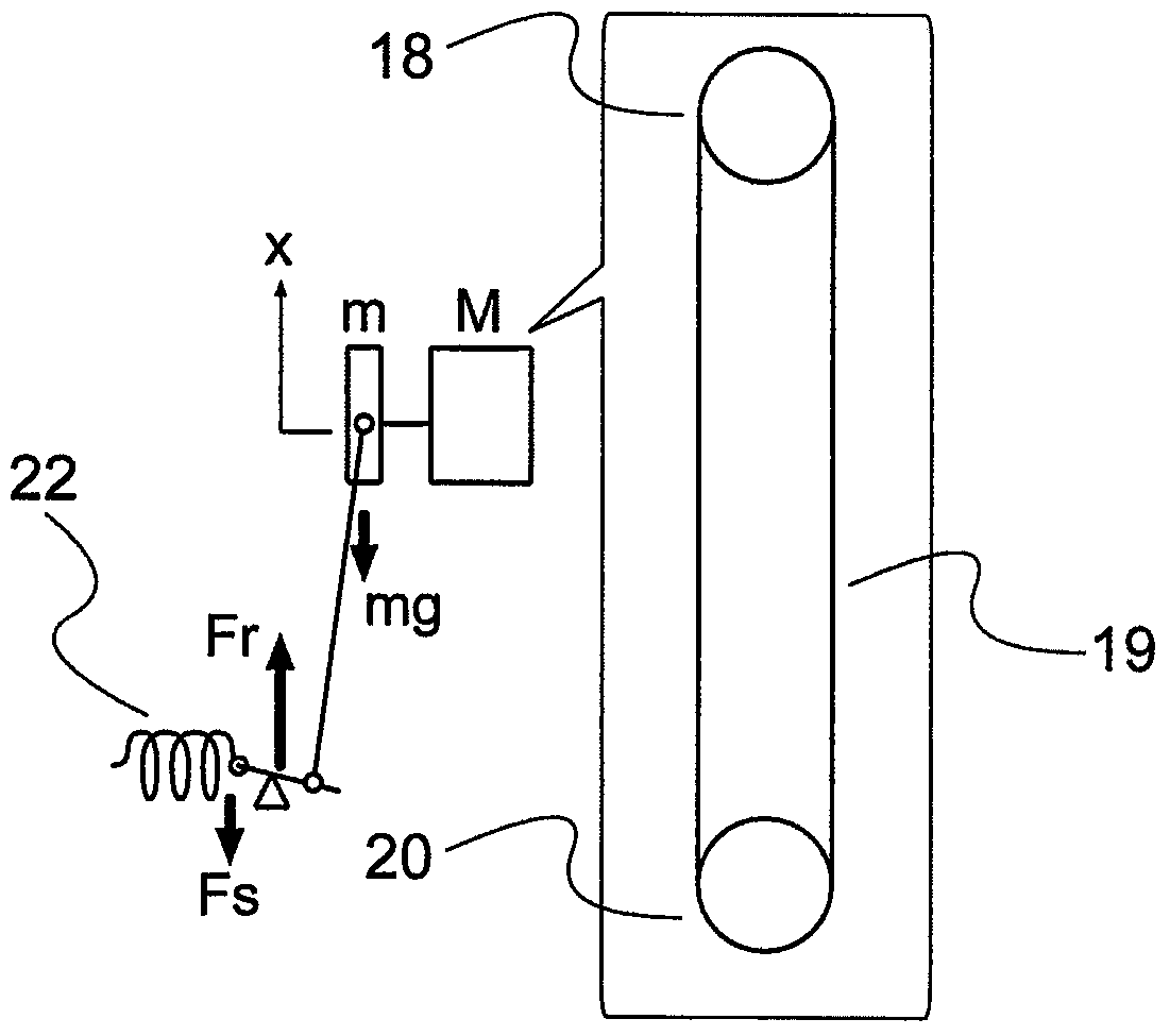
[0064] under, Figure 8 It is a block diagram schematically showing a main part of an elevator apparatus according to Embodiment 2 of the present invention, Figure 9 is showing Figure 8 The top view of the car 9. A pair of pins 31 serving as guides are erected on the top of the car 9 . Also, a pair of support springs 32 surrounding the pin 31 are provided on the upper surface of the car 9 .
[0065] A pair of grip levers (weight bodies) 33 facing each other are supported by support springs 32 . The support spring 32 is provided between the grip rod 33 and the car 9, and is initially compressed by the grip rod 33 in normal times. In addition, in a normal state, the pin 31 penetrates the grip rod 33 , and the grip rod 33 can move up and down along the pin 31 .
[0066] Such as Figure 9 As shown, the part of the opposite side of the side connected to the action lever 16 of the speed governor rope 19 is arranged between the handle bars 33, wherein the side and the opposit...
PUM
 Abstract
Description
Claims
Application Information