
Electric main shaft of turning and milling composite machine tool

A compound machine tool and electric spindle technology, which is applied in the direction of metal processing machinery parts, large fixed members, maintenance and safety accessories, etc., can solve the problems of inflexible start and stop, reduced life, low power, etc., and achieve good cooling effect and efficiency High, fast start-up effect

Inactive Publication Date: 2015-03-11
GUANGZHOU HAOZHI ELECTROMECHANICAL
View PDF9 Cites 7 Cited by
  • Summary
  • Abstract
  • Description
  • Claims
  • Application Information

AI Technical Summary

Problems solved by technology

The current motorized spindles generally have low power, especially those used in turning-milling machine tools. Due to the influence of heat and structural volume, the shaft core cannot obtain too much power and make it rotate too fast, otherwise the service life will be greatly reduced. Moreover, if the shaft core obtains a very high speed, it can only stop by its own friction, which takes a long time and low efficiency. Therefore, its start and stop are not flexible enough

Method used


Image

  • Electric main shaft of turning and milling composite machine tool

Examples


Embodiment Construction

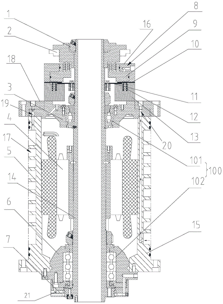
[0017] Such as figure 1 The electric spindle of a turning-milling compound machine tool shown includes a body 15, a shaft core 14, a rotor assembly 4, a stator assembly 5, a brake cylinder 8, a first stop ring 10, a second stop ring 11, a spring 12 and a fixed The seat 13, the shaft core 14 is pierced through the body 15 and pivotally connected with the body 15 through the bearing group 100, the stator assembly 5 is fixed on the inner wall of the body 15, the rotor assembly 4 is fixedly sleeved on the outer periphery of the shaft core 14 and is located in the stator assembly 5, The fixed seat 13 is fixed on the upper end of the body 15 and surrounds the outer side of the shaft core 14. The brake cylinder 8 includes a cylinder body 16 and a piston 9 installed in the cylinder body 16 to move telescopically along the axial direction of the shaft core 14. The cylinder body 16 and the fixed seat 13 is fixed, the first stop ring 10 is located between the bottom surface of the piston...


PUM


Abstract

The invention discloses an electric main shaft of a turning and milling composite machine tool. The electric main shaft comprises a machine body, a shaft core, a rotor component and a stator component, and further comprises a brake oil cylinder, a first stop ring, a second stop ring, a spring and a fixed base, wherein the fixed base is fixed at the upper end of the machine body, and is encircled at the outer side of the shaft core; the brake oil cylinder comprises a cylinder body, and a piston mounted in the cylinder body and extending in the axial direction of the shaft core; the cylinder body is fixed with the fixed base; the first stop ring is positioned between the bottom surface of the piston and the top surface of the fixed base; the second stop ring is positioned between the bottom surface of the first stop ring and the top surface of the fixed base, is fixedly connected with the shaft core in the radial direction, and is laminated with the first stop ring; the spring is positioned in the fixed base, upwards extends outside from the top surface of the fixed base in the axial direction, and ejects the first stop ring; and a spiral cooling water runner is formed in the wall body of the machine body for filling cooling water to cool the machine body. Under the condition of not shortening the service life, the electric main shaft realizes high-power rotation and high rotating speed.

Description

technical field [0001] The invention relates to an electric spindle, in particular to an electric spindle for a turning-milling compound machine tool. Background technique [0002] The electric spindle is a technology that integrates the machine tool spindle and the spindle motor in the field of CNC machine tools. The current motorized spindles generally have low power, especially those used in turning-milling machine tools. Due to the influence of heat and structural volume, the shaft core cannot obtain too much power and make it rotate too fast, otherwise the service life will be greatly reduced. and, if the shaft core obtains a very high speed, it can only stop by its own friction, which takes a long time and has low efficiency. Therefore, its start and stop are not flexible enough. Contents of the invention [0003] In order to overcome the deficiencies of the prior art, the object of the present invention is to provide an electric spindle of a turning-milling compoun...

Claims


Application Information

Patent Timeline
Patent Type & Authority Applications(China)
IPC IPC(8): B23B19/02B23Q11/12
CPCB23Q1/70B23Q11/127
Inventor 汤秀清黎训学
Owner GUANGZHOU HAOZHI ELECTROMECHANICAL
Learn More