Driven slide carriage for numerical-control cutting machine

A cutting machine and slide plate technology, applied in welding/cutting auxiliary equipment, auxiliary equipment, gas flame welding equipment, etc., can solve the problems of poor stability, unreasonable design, unsuitable for production, etc., and achieve reasonable structural design and installation Ease of maintenance and ensuring cutting stability

Inactive Publication Date: 2015-03-11
WUXI HENGFU TECH
View PDF5 Cites 0 Cited by
  • Summary
  • Abstract
  • Description
  • Claims
  • Application Information

AI Technical Summary

Problems solved by technology

However, the structure design of the traditional driven slide plate used on the CNC cutting machine is unreasonable and the stability

Method used


Image

  • Driven slide carriage for numerical-control cutting machine
  • Driven slide carriage for numerical-control cutting machine
  • Driven slide carriage for numerical-control cutting machine

Examples


Embodiment Construction

[0015] The present invention will be further described below in conjunction with specific drawings and embodiments.

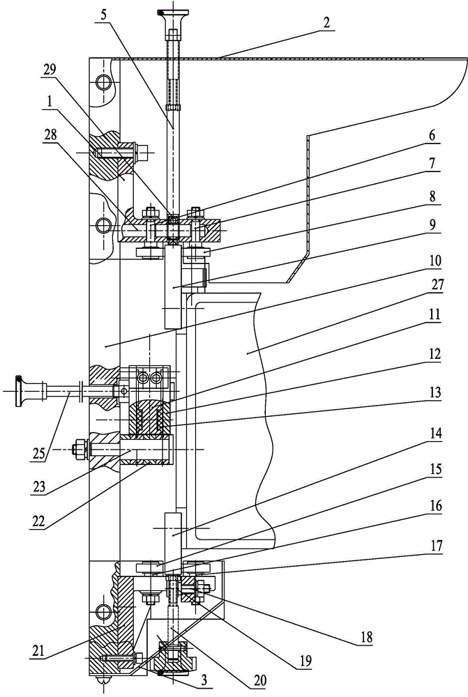
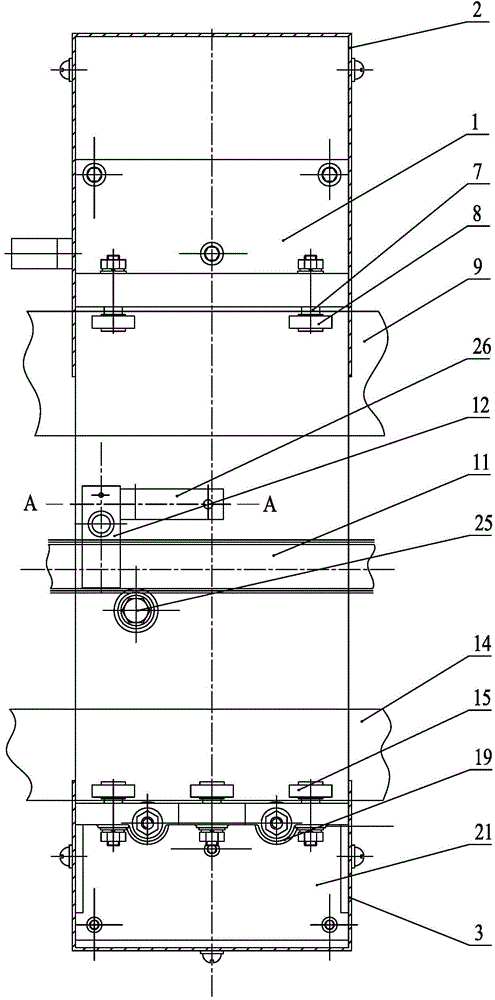
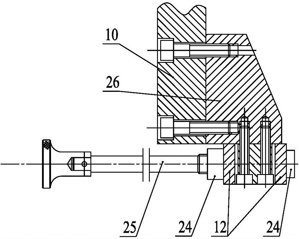
[0016] As shown in the figure, the driven slide plate in the embodiment is installed on the crossbeam 27 of the CNC cutting machine, and the upper and lower sides of the crossbeam 27 are respectively provided with an upper slide plate 9 and a lower slide plate 14; the driven slide plate is mainly composed of The front plate 10 and the lower support mechanism installed on the front plate 10, the upper support mechanism, the sliding plate locking mechanism and the auxiliary locking mechanism etc. are composed.

[0017] The structure of the upper supporting mechanism is as follows: figure 1 , figure 2 As shown, it is mainly composed of an upper bracket 1, an upper support shaft 28, an upper support bearing 29, an upper fixed shaft 7, an upper eccentric shaft 6 and an upper bearing 8. The upper bracket 1 is fixedly installed on the side wall of the front plate 1...


PUM


Abstract

The invention relates to a driven slide carriage for a numerical-control cutting machine. The driven slide carriage comprises a front plate, as well as a lower supporting mechanism and an upper supporting mechanism which are arranged on the front plate; in the upper supporting mechanism, an upper bracket is fixedly arranged on the side wall of the front plate, the upper bracket is provided with a row of upper bearing shafts which are transversely arranged, and the upper supporting shafts are provided with upper supporting bearings; one side of each upper supporting bearing is provided with a row of upper fixed shafts, and the other side of each upper supporting bearing is provided with a row of upper eccentric shafts; the upper ends of the upper fixed shafts and the upper eccentric shafts are respectively provided with upper bearings; in the lower supporting mechanism, a lower bracket is fixedly arranged on the side wall of the front plate and is provided with a row of transversely-arranged lower eccentric supporting shafts; the lower eccentric supporting shafts are provided with lower supporting bearings used for supporting slide plates; one side of each lower supporting bearing is provided with a row of lower fixed shafts, and the other side of each lower supporting bearing is provided with a row of lower eccentric shafts; the upper ends of the lower fixed shafts and the lower eccentric shafts are respectively provided with lower bearings. The driven slide carriage is reasonable in structural design, safe and reliable, convenient in installation and maintenance and capable of ensuring the cutting stability.

Description

technical field [0001] The invention relates to a driven sliding plate applied to a numerical control cutting machine, belonging to the technical field of welding and cutting equipment. Background technique [0002] CNC cutting machine is a kind of cutting equipment widely used in machinery industry. With the development of economy, the degree of automation of production equipment is getting higher and higher, and the quality requirements for cutting products are also getting higher and higher. The driven slide is a device used to transport the workpiece on the CNC cutting machine, and the accuracy and stability of its transport have an important impact on the cutting quality. However, the structure design of the traditional driven slide plate applied to the CNC cutting machine is unreasonable and the stability is poor, which leads to the low cutting accuracy of the CNC cutting machine and gradually does not meet the production requirements. Contents of the invention [0...

Claims


Application Information

Patent Timeline
IPC IPC(8): B23Q7/00B23K37/00
CPCB23K7/10
Inventor 周琦琪徐峰
Owner WUXI HENGFU TECH
Why Eureka
Try Eureka