A stable circular cutting mechanism

A cutting mechanism, circular technology, used in metal processing machinery parts, metal processing equipment, maintenance and safety accessories, etc., can solve the problems of unstable cutting fluid outflow, affecting the cutting effect of the cutter, and ensure cutting stability. Effect

Active Publication Date: 2021-08-13
常州鑫琪机械制造有限公司
View PDF0 Cites 0 Cited by
  • Summary
  • Abstract
  • Description
  • Claims
  • Application Information

AI Technical Summary

Problems solved by technology

[0002] The existing circular cutting mechanism drives the cutter to rotate through a rotating disc to perform circular cutting. At the same time, during the cutting process, the cutting fluid is sprayed to the cutter to cool down the cutter to ensure the stability of the cutter. Cutting effect, but there are still the following problems, the cutting fluid is unstable, and the cutting effect of the cutter will still be affected after the cutting fluid is blocked.

Method used


Image

  • A stable circular cutting mechanism
  • A stable circular cutting mechanism
  • A stable circular cutting mechanism

Examples


Embodiment 1

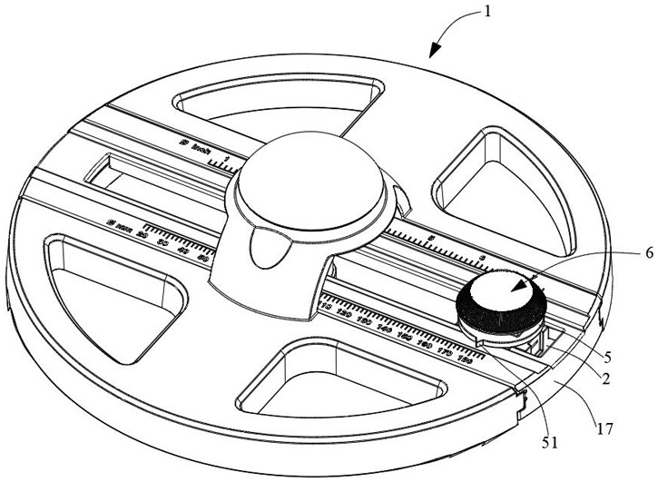
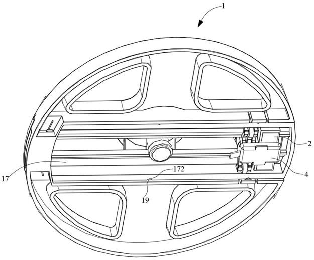
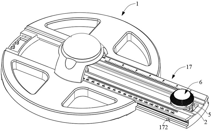
[0036] like Figure 1 to Figure 11 As shown, the existing circular cutting mechanism includes: a base 1, the base 1 is circular, and the center of the base 1 is provided with a rotating shaft 11, the specific installation method of the rotating shaft 11 is as follows: set up at the center of the upper end surface of the base 1 An arched top frame 12, the rotating shaft 11 passes through the top frame 12 and is rotatably connected with the top frame 12, the rotating shaft 11 passes through the base 1 downwards and protrudes from the lower end surface of the base 1, and a supporting sleeve is provided outside the lower half rotating shaft 11 13. The rotating shaft 11 is rotatably connected with the supporting sleeve 13. The supporting sleeve 13 is used to support on the cutting plane. A rotating knob 14 is fixed on the top of the rotating shaft 11. The rotating knob 14 is a quarter sphere. By rotating The top frame 12 realizes the rotation of the base 1. In order to ensure the s...

Embodiment 2

[0067] On the basis of the first embodiment, the second embodiment also provides a method for using a stable circular cutting mechanism, wherein a stable circular cutting mechanism is the same as the first embodiment, and will not be repeated here.

[0068] Further, remove the knife cover 4, and insert the insertion slot 25 through the plug block 42, so that the knife cover 4 is hung on the side wall of the sliding seat 2; push the sliding seat 2 to slide, and push the blocking block 46 to the stopper through the top block 26. The plate 47 is separated from the inner side wall of the receiving groove 43, so that the cutting fluid in the receiving groove 43 flows back into the liquid storage chamber 21; the cutting fluid is added to the liquid storage chamber 21 through the liquid inlet 49; the sliding seat is reversely pushed 2 Slide to make the pointer 51 point to the preset position; turn the finger ring 5 until the through hole 271 is opposite to the liquid outlet channel 22...


PUM


Abstract

The present invention relates to the technical field of machine tool processing, in particular to a stable circular cutting mechanism, comprising: a base, a sliding seat radially sliding along the base, and a cutter fixed at the bottom of the sliding seat; and the sliding There is a liquid storage chamber inside the seat, and a liquid storage sleeve is rotatably connected to the liquid storage chamber, and the liquid storage sleeve is suitable for storing cutting fluid; a liquid outlet channel is provided in the sliding seat, and the liquid outlet One end of the channel communicates with the liquid storage chamber, and the other end of the liquid outlet channel faces the cutter; a locking assembly is also provided inside the sliding seat, and the locking assembly extends above the sliding seat ; where the liquid storage sleeve is rotated until the liquid outlet channel is connected, the locking assembly can lock the liquid storage sleeve. To ensure the stable discharge of cutting fluid, thereby ensuring cutting stability.

Description

technical field [0001] The invention relates to the technical field of machine tool processing, in particular to a stable circular cutting mechanism. Background technique [0002] The existing circular cutting mechanism drives the cutter to rotate through a rotating disc to perform circular cutting. At the same time, during the cutting process, the cutting fluid is sprayed to the cutter to cool down the cutter to ensure the stability of the cutter. Cutting effect, but there are still the following problems, the cutting fluid is unstable, and the cutting effect of the cutter will still be affected after the cutting fluid is blocked. [0003] In order to solve the above problems, it is necessary to design a stable circular cutting mechanism. Contents of the invention [0004] The object of the present invention is to provide a stable circular cutting mechanism. [0005] In order to solve the above technical problems, the present invention provides a stable circular cutting...

Claims


Application Information

Patent Timeline
Patent Type & Authority Patents(China)
IPC IPC(8): B23Q11/10
CPCB23Q11/10
Inventor 秦志锋
Owner 常州鑫琪机械制造有限公司
Why Eureka
Try Eureka