Rubber-tube clamping linkage apparatus

A linkage device and clamping device technology, applied in the field of mechanical clamping, can solve the problems of slow speed and low efficiency

Active Publication Date: 2015-03-11
GUANGXI UNIV
View PDF4 Cites 5 Cited by
  • Summary
  • Abstract
  • Description
  • Claims
  • Application Information

AI Technical Summary

Problems solved by technology

[0004] The technical problem to be solved by the present invention is to provide a rubber hose stamping and clamping device with automatic positioning and clamping to ensure coaxiality and accuracy, so as to overcome the defects of the existing clamping technology and solve the problem of slow speed and high efficiency of the traditional manual assembly method. Low problems and protect workers' hand health

Method used


Image

  • Rubber-tube clamping linkage apparatus
  • Rubber-tube clamping linkage apparatus
  • Rubber-tube clamping linkage apparatus

Examples


Embodiment Construction

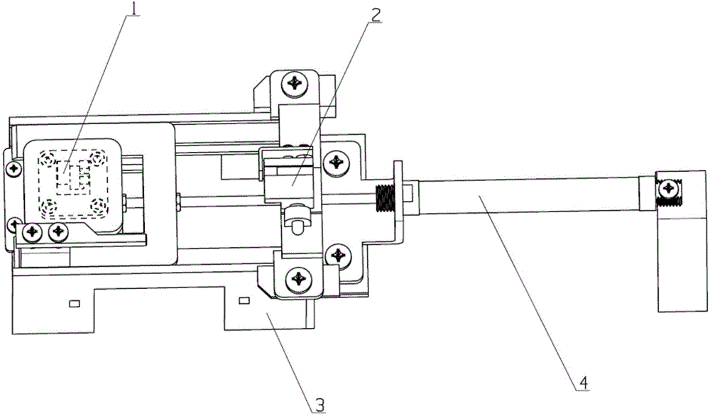
[0023] Such as figure 1 and Figure 7 As shown, a rubber hose clamping linkage device of the present invention includes a stamping mechanism 1, a clamping device 2, a fixed worktable 3 and a cylinder 4, and the stamping mechanism 1 is screwed to the piston rod end 41 of the cylinder 4 through a first nut 401 , the clamping device 2 is installed on the fixed workbench 3 through double screws, and the cylinder 4 is installed on the fixed workbench 3 horizontally.

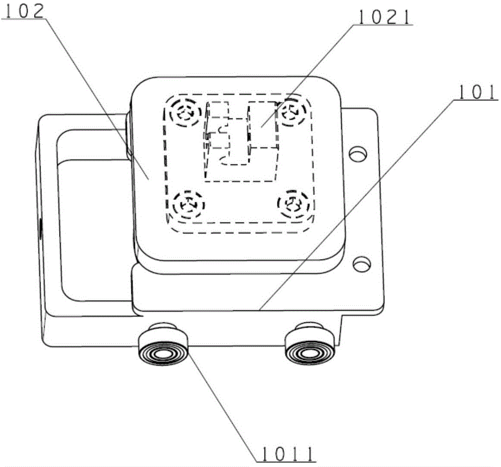
[0024] Such as figure 2 As shown, the stamping mechanism includes a feed trolley 101 and a joint installation platform 102. The feed trolley 101 is designed and installed on the second slide rail 304 of the fixed workbench 2 with bilateral symmetrical rollers 1011. The joint installation platform 102 is provided with a rubber hose joint clamp The holding structure 1021 is used for multi-station joint installation. The joint installation table 102 is installed on the feed trolley 101, and the feed trolley 101 passes...


PUM


Abstract

A rubber-tube clamping linkage apparatus comprises a stamping mechanism, a clamping device, a stationary work table and a cylinder installed on the stationary work table; the internal side of the stationary work table is provided with a first slide rail and a second slide rail; the clamping device comprises a rubber-tube clamping mechanism with a baffle plate and a locking mechanism; the rubber-tube clamping mechanism with the baffle plate utilizes a rubber-tube placing stationary table frame and a positioning baffle plate to realize positioning of a rubber tube; the locking mechanism utilizes a self-locking mechanism with a spring, a locking rod member and a feeding table with a positioning hole to realize tight clamping of the rubber tube; and a joint installation table is installed on a feeding dolly of the stamping mechanism, and the feeding dolly is tightly screwed at the end part of a piston rod of the cylinder through a nut, and is installed on the second slide rail through a double-flange symmetric roller. The rubber-tube clamping linkage apparatus is easy to install, easy to operate and low in cost, is capable of reducing labor intensity of workers, and has relatively good usage value and popularization potential.

Description

technical field [0001] The invention relates to the field of mechanical clamping, in particular to a rubber hose clamping linkage device. Background technique [0002] The process of assembling the joints of the existing rubber hoses generally adopts a manual assembly method, that is, manually holding the end of the rubber hose with one hand and holding the joint with the other hand to forcefully insert the joints into the inside of the rubber hose. Its disadvantages are that the manual operation is low, the work efficiency is unstable, and long-term work will cause great damage to the human hand, especially in the cold winter, pure manual operation cannot maintain the normal operation of the enterprise. [0003] With the advancement of science and the actual needs of enterprises, many enterprises have devoted themselves to the development of automatic assembly devices for rubber hose joints to achieve large-scale and high-efficiency production. The clamping of the rubber h...

Claims


Application Information

Patent Timeline
Patent Type & Authority Applications(China)
IPC IPC(8): B29C65/56
Inventor 廖小平刘祥沙欧诚意郑广平龙凤英邓耀国卓雪艳林海荣韦佳洵
Owner GUANGXI UNIV
Why Eureka
Try Eureka