Back column upper decoration plate and mold and injection molding method thereof

A technology for a decorative plate and a rear pillar, which is applied to the decorative plate on the rear pillar and its mold and injection molding fields, can solve problems such as inability to solve surface air trapping, and achieve the effects of simple structure, low cost, and easy realization.

Active Publication Date: 2015-03-11
CHENGDU AEROSPACE MOLD & PLASTIC CO LTD
View PDF4 Cites 2 Cited by
  • Summary
  • Abstract
  • Description
  • Claims
  • Application Information

AI Technical Summary

Problems solved by technology

[0011] The purpose of the present invention is to provide the decorative plate on the rear pillar and its mold and injection molding method, to solve the traditional (before improvement) decorative plate on the rear pillar and its mold and injection molding method in the debugging method that usually solves the trapped air, improve the injection pressure, Injection speed, melt temperature and other methods cannot solve the problem of trapped air on the surface of the product near the deep hole structure, causing air marks and other appearance defects

Method used


Image

  • Back column upper decoration plate and mold and injection molding method thereof
  • Back column upper decoration plate and mold and injection molding method thereof
  • Back column upper decoration plate and mold and injection molding method thereof

Examples


Embodiment Construction

[0037] The specific embodiments of the present invention will be described in detail below in conjunction with the accompanying drawings.

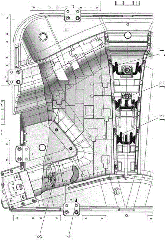
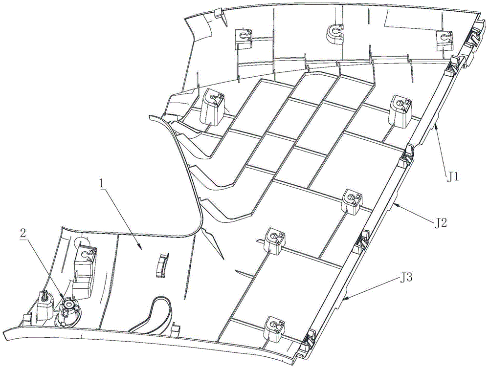
[0038] Such as Figure 4 As shown, the decorative plate 1 on the rear pillar has improved the deep hole structure 2, and cleverly connects the original two pillar decoration cover hook holes 23 with the two mounting screw lookout holes 22 corresponding to their respective positions, thereby forming a structure for Blocking material flow 3. the choke hole 24 that flows through in the deep hole.

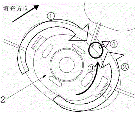
[0039] Such as Figure 5 As shown, the improved deep hole structure 2 changes the filling order of the material, so that the two strands of material ① and ② converge first, and then flow downward—forming material flow ③, ④—converging at the bottom of the deep hole structure cavity 31 , here is the exhaust position of the deep hole structure movable mold 3, which solves the defect of trapped air. After mold modification, the mold test was verifie...


PUM


Abstract

The invention discloses a back column upper decoration plate and a mold and an injection molding method of the back column upper decoration plate. A deep-hole structure is arranged on the back column upper decoration plate and comprises hole side walls, wherein structures for preventing material flow from passing through the hole side walls are arranged on the hole side walls on two opposite sides. The mold of the back column upper decoration plate comprises a deep-hole structure cavity, wherein a flow choking hole forming block for forming a flow choking hole is respectively arranged on two side walls of the deep-hole structure cavity. The injection molding method of the back column upper decoration plate comprises the steps of adjusting the material flow direction to enable the two flow choking hole forming blocks to be respectively located on two sides of the material flow direction, enabling material flow 1 and material flow 2 to be converged in advance, enabling the material flow to flow downwards to be converged at the top of the deep-hole structure, and enabling air to be discharged through an exhaust mechanism at the bottom of the deep-hole structure cavity so as to avoid air trapping. The defects of air marks on the product surface nearby the deep-hole structure and other appearance problems are overcome, a product with good appearance is obtained, and batch production is successively achieved. In addition, the improved portion of the mold is simple in structure and easy to achieve, and only a little cost is increased.

Description

technical field [0001] The invention relates to a decorative plate on a rear pillar of an automobile, a mold thereof and an injection molding method thereof. Background technique [0002] As consumers have higher requirements for car appearance and functions, car interior parts have to take on more and more roles, especially in large interior plastic parts such as rear pillar decorative panels, not only to meet their own decoration function, it may also need to provide positioning and support for other products, so the structure becomes complex, and many deep hole structures appear; usually the role of the deep hole structure mainly includes: the screw holes required for the positioning of the interior parts themselves; decoration Components such as handle boxes, ashtrays, cup holders and other structures; and positioning holes required by other products. In order to meet their functions, these structures are often small in size and deep in depth. Usually, when the deep ho...

Claims


Application Information

Patent Timeline
Patent Type & Authority Applications(China)
IPC IPC(8): B60R13/02B29C45/26B29C45/27B29C45/34B29L31/58
CPCB29C45/2602B29C45/2708B29C45/34B29L2031/58B60R13/025
Inventor 蔡淑琼刘尚进李芬李新
Owner CHENGDU AEROSPACE MOLD & PLASTIC CO LTD
Why Eureka
Try Eureka