
Detachable tape coiling device

A detachable and tape-reeling technology, which is applied in the directions of winding strips, transportation and packaging, thin material processing, etc., can solve the problems of excessively loose tapes, increase costs, reduce the profit of label edge materials, etc., and achieve convenient placement and transportation , the effect of reducing the occupied space

Inactive Publication Date: 2015-03-11
CHONGQING JINGANG MACHINERY
View PDF5 Cites 2 Cited by
  • Summary
  • Abstract
  • Description
  • Claims
  • Application Information

AI Technical Summary

Problems solved by technology

[0003] The existing tape device is generally composed of a motor to drive the reel to rotate. During the process of conveying the label edge material to the tape reel system, the conveying speed changes, ranging from fast to slow. When the label edge material is conveyed slowly, the label edge If the material reel is too tight, it is difficult to separate the label edge from the reel. If the entire roller is disassembled and sold together with the label edge, you need to prepare a lot of rollers, which will obviously increase your own cost and reduce the label edge. The profit from the sale of the label material; when the label material is conveyed quickly, the label material tape is too loose, and the stored label material is easy to loose, and the label material of the same length will occupy a relatively large space. Easy to place and transport

Method used


Image

  • Detachable tape coiling device
  • Detachable tape coiling device
  • Detachable tape coiling device

Examples


Embodiment Construction

[0013] Below in conjunction with accompanying drawing and specific embodiment the present invention will be described in further detail:

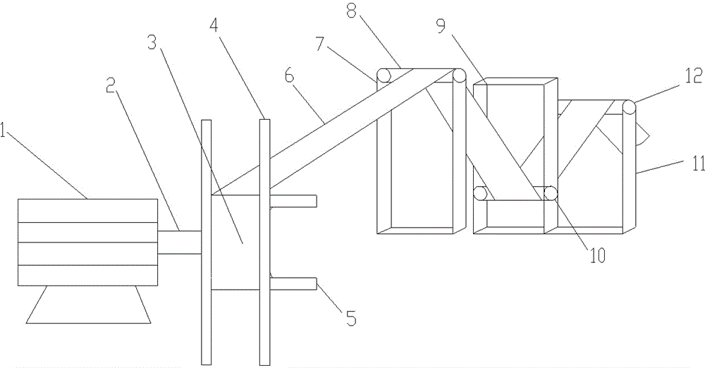
[0014] Such as figure 1 As shown, a detachable tape winding device includes a motor 1, a motor shaft 2, a reel 3, a movable baffle 4, a handle 5, a label trim 6, a matching iron frame 7 and a roller 8, and an iron frame 9 And drum 10, iron frame 11 and drum 12;

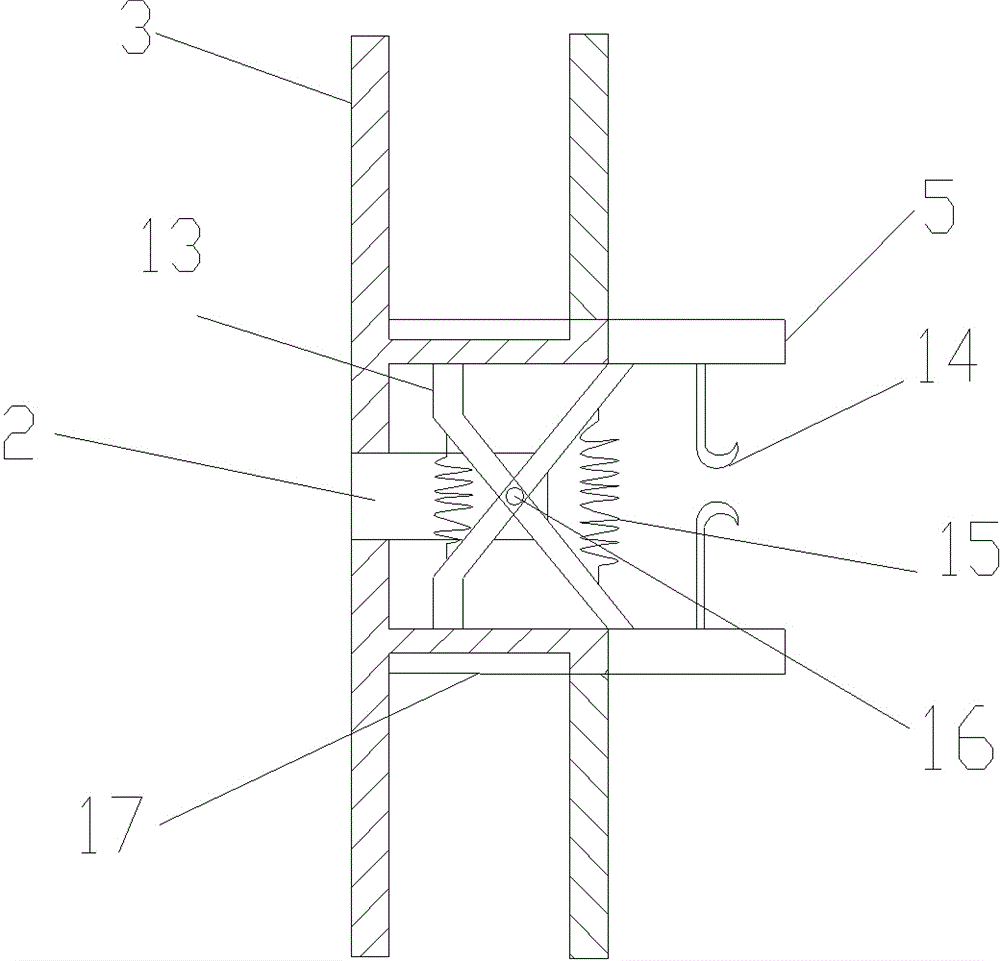
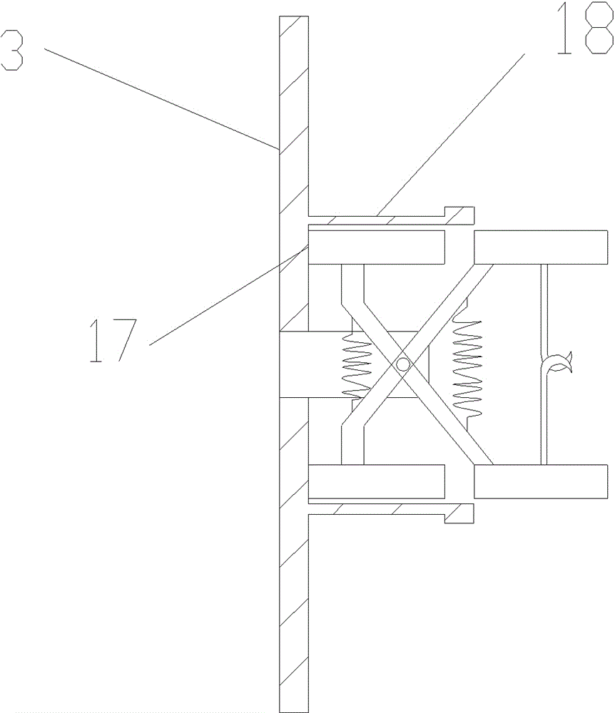
[0015] Such as figure 2 As shown, the inside of the reel 3 is provided with a connecting rod 13 and a gap 18, the connecting rod is provided with a spring 15, a positioning pin 16, a gap stopper 17, and the handle 5 is provided with a hook 14.

[0016] As a preferred solution:

[0017] Such as figure 1 , Figure 4 As shown, the iron frames 7, 9, 11 are all connected by iron bars, and the drums 8, 10, 12 are of the same structure, and the inside is respectively provided with a rotating shaft 20, and the two sides of the rotating shaft 20 are respectively provided with retainin...


PUM


Abstract

The invention relates to a tape coiling device, in particular to a detachable tape coiling device. The tape coiling device comprises a motor, a reel and iron racks, wherein the reel is connected with the motor; the iron racks are connected to the reel through a label scrap; the reel consists of a circular tube and a movable baffle plate; one end of the circular tube is provided with a fixed baffle plate; the movable baffle plate is arranged on the external diameter of the other end of the circular tube in a sleeving manner; the part between the two baffle plates of the circular tube is provided with notches in longitudinal symmetry; notch stop blocks are arranged in the circular tube corresponding to the notches and are fixedly arranged at the tail ends on certain sides of connecting rods respectively; the tail ends on the other sides of the connecting rods are provided with handles respectively; hooks are arranged between the handles; the motor is provided with a motor rotating shaft which is fixed to the reel; the motor rotating shaft is provided with a positioning pin for connecting a crossing point of the connecting rods; a spring is arranged between the connecting rods on the two sides of the positioning pin; the iron racks are provided with drums which are fixedly arranged on the tops of the iron racks and slide up and down in the iron racks. The device has the beneficial effects that the label scrap can be coiled tightly and meanwhile can be very easily separated from the reel.

Description

technical field [0001] The invention relates to a tape winding device, in particular to a detachable tape winding device. Background technique [0002] The take-up device is a device that fixes one end of the label edge material on the drum, and then drives the drum to rotate through the motor, so that the label edge material is stored in a roll, so as to achieve a device that is convenient for placement and transportation. In the labeling process of agricultural machinery, it is often necessary to cut off the edge of the label to form a label trim, and the label trim can generally be stored in a roll by a tape-reeling device, which is convenient for sale to other companies. [0003] The existing tape device is generally composed of a motor to drive the reel to rotate. During the process of conveying the label edge material to the tape reel system, the conveying speed changes, ranging from fast to slow. When the label edge material is conveyed slowly, the label edge If the ...

Claims


Application Information

Patent Timeline
IPC IPC(8): B65H18/02
CPCB65H18/02B65H18/10
Inventor 张长贵
Owner CHONGQING JINGANG MACHINERY
Learn More