
A multifunctional creel system

A creel and multi-functional technology, applied in the direction of conveying filamentous materials, thin material processing, transportation and packaging, etc., can solve the problems of inaccurate control, inability to adjust the position, and non-adjustable position, so as to avoid yarn wear, Ease of use and simple structure

Active Publication Date: 2017-02-22
ZHEJIANG KAICHENG TEXTILE MACHINERY
View PDF11 Cites 0 Cited by
  • Summary
  • Abstract
  • Description
  • Claims
  • Application Information

AI Technical Summary

Problems solved by technology

However, because the position of the groove is fixed, the creel can only be fixed at a certain position, and the position cannot be adjusted according to the needs of users
[0004] At the same time, the above-mentioned creel usually uses friction rollers to drive the yarn bobbin to rotate, so as to realize winding, which is easy to cause wear of the yarn, and the control is not accurate
[0005] Invention Patent No. 201420209943.0 of the People's Republic of China discloses a creel that is actively wound and formed. However, this creel can only use one type of yarn bobbin, which causes a lot of inconvenience in use. If the entire creel is replaced as a whole, it will cause Increase in equipment cost
[0006] The existing creel still has many defects such as non-adjustable position, only yarn bobbins of specific length and shape, low degree of automation, and inconvenient edge control.

Method used


Image

  • A multifunctional creel system
  • A multifunctional creel system
  • A multifunctional creel system

Examples


Embodiment Construction

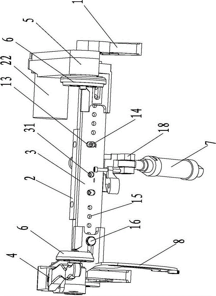
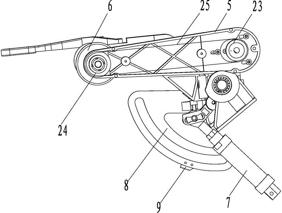
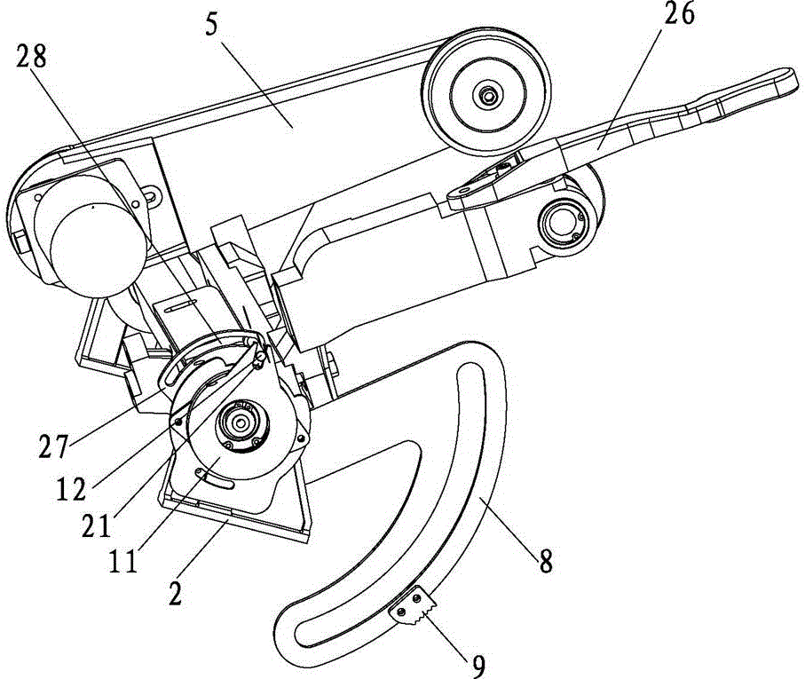
[0030] Please refer to the attached figure 1 to attach Figure 7 As shown, the present invention is a multifunctional creel system, which consists of a frame 1, a base plate 2, a mounting plate 3, a left arm 4, a right arm 5, a top plate 6, a cylinder 7, a rotating arm 8, a clamping plate 9, Movable support plate 10, potentiometer 11 and driving lever 12 etc. are made up of several parts.

[0031] Wherein, the base plate 2 is pivotally connected to the frame 1 so that it can be turned upside down.

[0032] The mounting plate 3 is pivotally connected to the base plate 2 through a pin shaft 31 , so that the mounting plate 3 can rotate relative to the base plate 2 . The mounting plate 3 is provided with an elliptical hole 13 on both sides of the pin shaft 12; a pair of screws 14 pass through the elliptical hole 13 and are screwed to the base plate 2, so as to realize the fixing of the base plate 2 and the mounting plate 2.

[0033] The mounting plate 3 is provided with several...


PUM


Abstract

The invention relates to a multifunctional bobbin creel system. A base plate of the multifunctional bobbin creel system is pivoted on a rack; an installation plate is pivoted on the base plate by virtue of a pin roll; the installation plate is equipped with an oval hole at each of two sides of the pin roll; a pair of screws gets through the oval holes, and is in threaded connection on the base plate; a plurality of installation holes are formed in the installation plate; a left arm and a right arm are arranged in the installation holes by virtue of bolts; top plates are resistively arranged on the left arm and the right arm; a gas cylinder is connected to the base plate for pushing the base plate to turn over; a rotary arm is fixedly arranged at one side of the base plate; a blocking plate is arranged on the rotary arm, and a saw-tooth structure is arranged on the blocking plate; a movable supporting plate is pivoted on the rack and capable of being engaged with the saw-tooth structure; a potentiometer is positioned at the outer side of the base plate, and an insertion slot is arranged on the potentiometer; a driving lever is arranged on the base plate, inserted to the insertion slot and capable of driving the potentiometer to rotate. The multifunctional bobbin creel system disclosed by the invention has the advantages of a simple structure, convenience in use, low cost, stable performance, capacity of producing different yarn bobbins, and the like.

Description

technical field [0001] The invention relates to a composition system of yarn production equipment, in particular to a multifunctional creel system, which belongs to the technical field of textile machinery. Background technique [0002] As we all know, the creel is an important component structure of the twisting equipment, which is used to install the yarn bobbin and rotate the yarn bobbin to wind the yarn into shape. [0003] Please refer to the invention patent No. 201120141306.0 of the People's Republic of China for the structure of the creel in the prior art. A groove is provided at the end of a pressurized slide bar to position the lifted creel. However, since the position of the groove is fixed, the creel can only be fixed at a certain position, and the position cannot be adjusted according to the needs of the user. [0004] At the same time, the above-mentioned creel usually uses a friction roller to drive the yarn bobbin to rotate to realize winding, which easily c...

Claims


Application Information

Patent Timeline
Patent Type & Authority Patents(China)
IPC IPC(8): B65H54/553
Inventor 张元刚
Owner ZHEJIANG KAICHENG TEXTILE MACHINERY
Learn More