Vacuum magnetron sputtering coating magnetic suspension transmission device and application method

A technology of vacuum magnetron sputtering and transmission device, which is applied in the field of magnetic transmission, and can solve the difficulty of adjusting the transmission accuracy of guide rail distance, verticality and parallelism, the easy wear and tear of rack and pinion, guide rail and trolley sliding wheel, and the qualified rate of production products Low and other problems, to achieve the effect of significant operation, improve product quality, and easy operation

Inactive Publication Date: 2015-03-11
LUOYANG KANGYAO ELECTRONICS
View PDF2 Cites 1 Cited by
  • Summary
  • Abstract
  • Description
  • Claims
  • Application Information

AI Technical Summary

Problems solved by technology

When passing through the buffer chamber, the distance, verticality, parallelism, and transmission accuracy between the guide wheel and the guide rail are difficult to adjust, and direct contact forms friction, which makes the rack and pinion, guide rail and trolley sliding wheel easy to wear
The stability of the trolley is very poor during operation. The way of advancement is through the hard contact between the gear and the rack. There is no shock absorption, and it is easy to vibrate and vibrate during operation.
In addition, when the track is deflected, the trolley is easy to derail, causing the trolley to crash into other equipment components inside the cavity, causing serious consequences
The trolley is directly connected to the chamber in the sputtering area of ​​the target, without forming insulation isolation, which makes the target easy to arc and jump during the sputtering process, which affects the stability of the equipment
As a result, the qualified rate of production products is low and the product quality is poor

Method used


Image

  • Vacuum magnetron sputtering coating magnetic suspension transmission device and application method
  • Vacuum magnetron sputtering coating magnetic suspension transmission device and application method

Examples


Embodiment 1

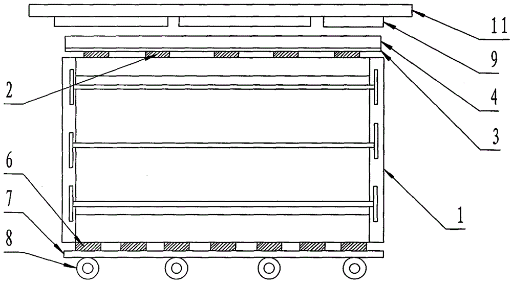
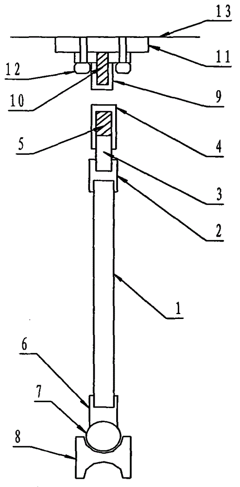
[0024] At least five upper insulating blocks 2 are arranged above the vehicle body 1, at least five lower insulating seats 6 are arranged below, and No. 1 magnetic shoe 3 is arranged between the top of the upper insulating block 2 and the inverted U-shaped magnet sheath 4, and the inverted U-shaped magnet A strong magnetic N pole 5 is set inside the sheath 4, a transmission guide rod 7 is set under the lower insulating seat 6, and the lower part of the drive guide rod 7 is set correspondingly to the transmission wheel 8 of the transmission system; a T-shaped magnet sheath is set above the inverted U-shaped magnet sheath 4 9. A magnetic field action space is reserved between the T-shaped magnet sheath 9 and the inverted U-shaped magnet sheath 4. The T-shaped magnet sheath 9 is provided with a strong magnetic S pole 10, and the T-shaped magnet sheath 9 is provided with a No. 2 magnetic shoe. 11. The T-shaped magnet sheath 9 is fixed on the No. 2 magnetic shoe 11 by screws 12, and...

Embodiment 2

[0026] The section of the upper insulating block 2 is H-shaped, and the upper and lower parts of the upper insulating block 2 form an upper and a lower card slot respectively, the lower card slot is set correspondingly to the top of the car body 1, and the upper card slot is connected to the No. 1 magnetic shoe 3 Corresponding settings below.

Embodiment 3

[0028] A magnet cavity is set in the T-shaped magnet sheath 9, and a strong magnetic S pole 10 is set in the magnet cavity; a magnet cavity is set in the inverted U-shaped magnet sheath 4, and a strong magnetic N pole 5 is set in the magnet cavity. The strong magnetic N pole 5 in the inverted U-shaped magnet sheath 4 corresponds to the top of the No. 1 magnetic shoe 3 .


PUM


Abstract

The invention discloses a vacuum magnetron sputtering coating magnetic suspension transmission device and an application method. The device consists of a trolley body, upper insulating blocks, a first magnetic solid boot, an inverted U-shaped magnet sheath, strong magnetic poles N, lower insulating seats, a transmission guide rod, transmission wheels of a transmission system, a T-shaped magnet sheath, strong magnetic poles S, a second magnetic solid boot and screws. The device is simple in structure, reasonable in design, convenient to operate, low in manufacturing cost and remarkable in running effect, improves the working efficiency and the quality of a product, and is applied to continuous substrate flow of vacuum magnetron sputtering coating equipment; the running stability, acceleration and deceleration performance and insulation performance of a trolley in a vacuum chamber are improved, the production quality of the product is remarkably improved, the production yield and the qualified rate are increased, an optimization process is remarkably improved, the failure rate of equipment is effectively lowered, and high-end equipment technological reformation in the vacuum magnetron sputtering coating equipment is achieved.

Description

technical field [0001] The invention relates to the technical field of magnetic transmission, in particular to a vacuum magnetron sputtering coating magnetic levitation transmission device and an application method. Background technique [0002] At present, in the vacuum magnetron sputtering coating equipment, the transmission of the glass-loaded substrate rack trolley is required to be stable, with good acceleration and deceleration, and good insulation from the vacuum chamber. Among the domestic or imported equipment, the gear transmission is commonly used in the early equipment, and the trolley directly contacts the guide rail. When passing through the buffer chamber, it is difficult to adjust the distance, verticality, parallelism and transmission accuracy between the guide wheel and the guide rail, and the direct contact forms friction, which makes the rack and pinion, guide rail and trolley sliding wheel easy to wear. The stability of the trolley is very poor during o...

Claims


Application Information

Patent Timeline
Patent Type & Authority Applications(China)
IPC IPC(8): C23C14/35C23C14/56C23C14/08
CPCC23C14/35C23C14/086C23C14/568
Inventor 王恋贵董安光谭华秦遵红
Owner LUOYANG KANGYAO ELECTRONICS
Why Eureka
Try Eureka