Combined in-situ shallow layer geotherm measurement drill

A combined and in-situ technology, which is applied to drill bits, drilling equipment, and earthwork drilling and production, can solve problems such as measurement error, in-situ measurement, soil disturbance, etc., and achieve the effect of convenient installation, disassembly and maintenance

Inactive Publication Date: 2015-03-11
JILIN UNIV
View PDF5 Cites 9 Cited by
  • Summary
  • Abstract
  • Description
  • Claims
  • Application Information

AI Technical Summary

Problems solved by technology

At present, in the field of shallow geothermal energy exploration technology at home and abroad, there are few instruments used for shallow geothermal measurement, and the temperature measurement method adopted by these existing instruments is mainly to use static pressure to press the penetrating device into the soil layer, and then press the penetration device into the soil layer. The temperature measuring probe is put into the penetrating device to measure the shallow ground temperature, but this method has the following two defects: one is that it causes strong disturbance of the soil layer, and the other is that the underground temperature measuring point is easily connected with the outside world, both of which will lead to There are errors in the measurement results, and in-situ measurement cannot be truly achieved

Method used


Image

  • Combined in-situ shallow layer geotherm measurement drill
  • Combined in-situ shallow layer geotherm measurement drill
  • Combined in-situ shallow layer geotherm measurement drill

Examples


Embodiment Construction

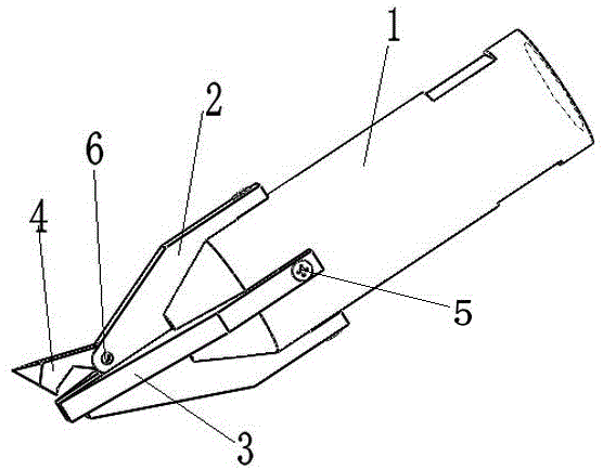
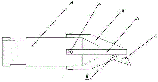
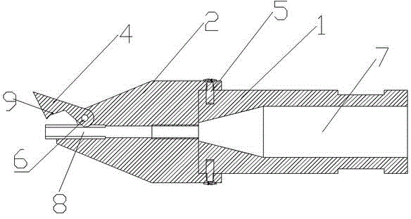
[0012] see figure 1 , figure 2 , image 3 , Figure 4 and Figure 5 As shown, this embodiment is composed of a drill body 1, a first cutting edge 2, a second cutting edge 3, a movable cone tip 4, a screw 5 and a pin 6. The front end of the drill body 1 is a conical structure and has a cross-shaped groove. The cone angle of the conical structure is 40°~60°. The first cutting edge 2 and the second cutting edge 3 are inserted into the cross-shaped groove and connected to the drill bit body 1 through the screw 5. The first cutting edge 2 and the second cutting edge 3 It is in the shape of a cross, and the maximum width of the first cutting edge 2 and the second cutting edge 3 is 3-5 mm larger than the outer diameter of the drill body 1 . The lower part of the movable cone point 4 is designed to be arc-shaped, and the movable cone point 4 is installed in the arc-shaped hole groove of the first cutting edge 2 through the pin 6. The movable cone point 4 is closely matched with t...


PUM


Abstract

The invention discloses a combined in-situ shallow layer geotherm measurement drill which is composed of a drill body, a first cutting edge, a second cutting edge, a movable conical tip, a screw and a pin. A conical structure is arranged at the front end of the drill body and is provided with a cross groove. The first cutting edge and the second cutting edge are inserted into the cross groove in a criss-cross mode to be connected with the drill body. The movable conical tip is installed in an arc-shaped hole groove of the first cutting edge through the pin and is closely matched with the first cutting edge. A through hole is formed in the drill body. Geotherm measurement probe placing through holes are formed in the first cutting edge and the second cutting edge and communicated with the through hole. The movable conical tip of the drill blocks the geotherm measurement probe placing through holes. The movable conical tip at the front end of the drill ensures that soil grains do not enter the drill to plug the hole in front of the drill during drilling, the stratum is not communicated with the outside, and the purpose of in-situ shallow layer geotherm measurement is achieved. The criss-cross cutting edges provide sufficient torque. The drill is of a combined structure and can be mounted, demounted and repaired conveniently.

Description

technical field [0001] The invention relates to a temperature measuring drill bit, in particular to a combined in-situ shallow ground temperature measuring drill bit. Background technique [0002] In recent years, non-renewable energy sources at home and abroad have become increasingly scarce, and shallow geothermal energy, as a clean, non-polluting, renewable new energy source, has attracted more and more attention from the whole society. At present, in the field of shallow geothermal energy exploration technology at home and abroad, there are few instruments used for shallow geothermal measurement, and the temperature measurement method adopted by these existing instruments is mainly to use static pressure to press the penetrating device into the soil layer, and then press the penetration device into the soil layer. The temperature measuring probe is put into the penetrating device to measure the shallow ground temperature, but this method has the following two defects: on...

Claims


Application Information

Patent Timeline
Patent Type & Authority Applications(China)
IPC IPC(8): E21B10/43E21B10/62E21B47/07
CPCE21B10/43E21B10/62E21B47/07
Inventor 张延军张通殷仁朝于子望胡忠君张驰谢洋洋刘彤
Owner JILIN UNIV
Why Eureka
Try Eureka