Multi-angle rotor fluid mechanism and engine using the same
A fluid mechanism, angular rotor technology, applied in machine/engine, combustion engine, internal combustion piston engine, etc., can solve problems such as processing difficulties and seal wear
- Summary
- Abstract
- Description
- Claims
- Application Information
AI Technical Summary
Problems solved by technology
Method used
Image

Examples
Embodiment 1
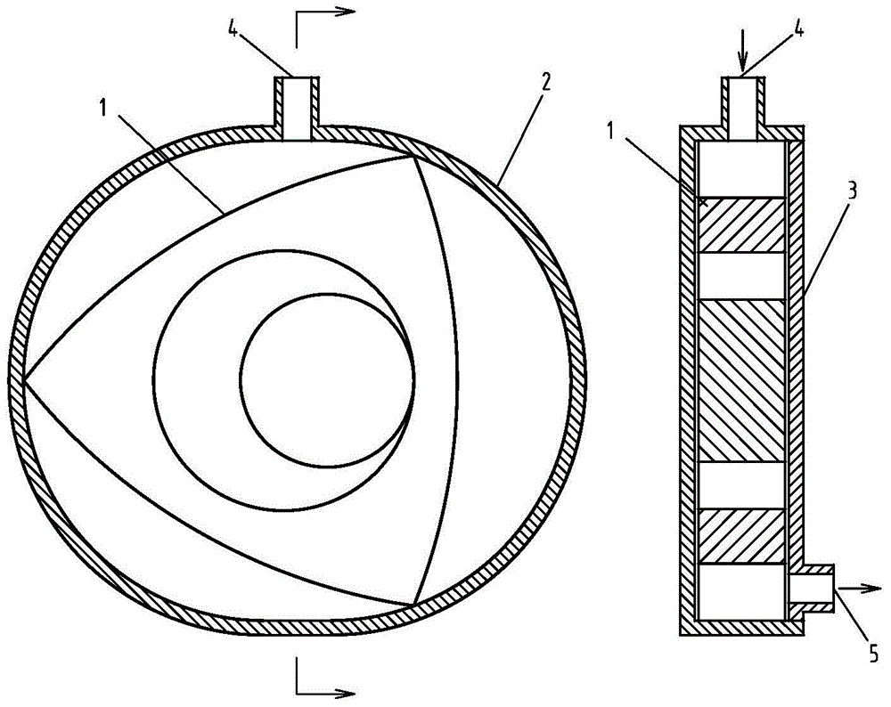
[0100] Such as figure 1 As shown, a multi-angle rotor fluid mechanism includes a triangular rotor 1, and the triangular rotor 1 is arranged in a double-arc cylindrical cavity 2. Between the double-arc cylindrical cavity 2 and the double-arc cylindrical cavity A fluid inlet 4 and a fluid outlet 5 are correspondingly arranged on the end sealing body 3 of 2.
[0101] In the present invention, the so-called "corresponding arrangement" is different from the air inlet and the exhaust port of the traditional triangular piston engine, and refers to setting the fluid inlet in one compression expansion area of the polygonal rotor fluid mechanism, and setting the fluid inlet in another The fluid outlet is set in a pressure expansion area, the pressure expansion area refers to the area where the volume decreases to the limit and the starting point of the volume begins to increase, including when the triangular rotor is near the pressure expansion area The area communicated with the com...
Embodiment 2
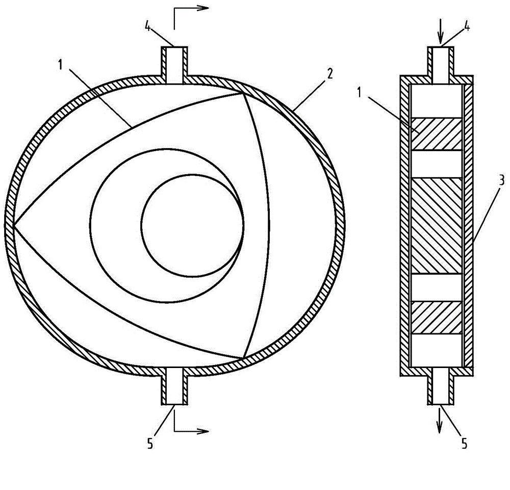
[0103] Such as Figure 2.1 As shown, a polygonal rotor fluid mechanism, on the basis of Embodiment 1: the fluid inlet 4 and the fluid outlet 5 are correspondingly arranged on the double-arc cylindrical cavity 2.
[0104] As a transformable implementation, such as Figure 2.2 As shown, the fluid inlet 4 and the fluid outlet 5 are correspondingly arranged on the end sealing body 3 of the double-arc cylindrical cavity 2 .
Embodiment 3
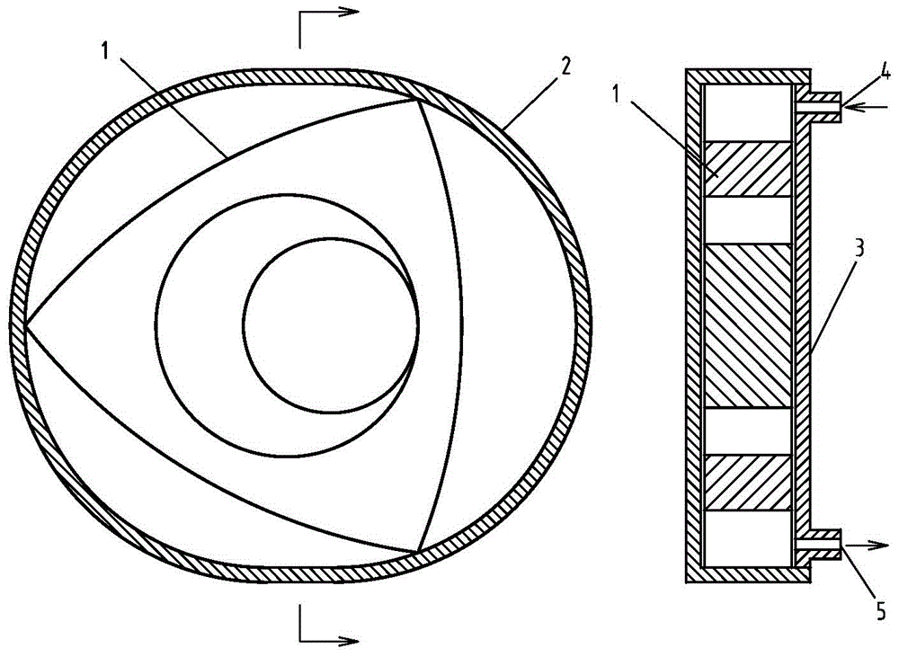
[0106] Such as image 3 As shown, a multi-angle rotor fluid mechanism differs from Embodiment 1 in that: the angle top 101 of the triangular rotor 1 and the inner wall of the double-arc cylindrical cavity 2 are arranged in non-contact sliding and sealing cooperation.
[0107] As a changeable embodiment, the corner top 101 of the triangular rotor 1 is arranged in contact with the inner wall of the double-arc cylindrical cavity 2 in a sliding and sealing manner.
PUM
 Abstract
Description
Claims
Application Information
 - R&D
- Intellectual Property
- Life Sciences
- Materials
- Tech Scout
- Unparalleled Data Quality
- Higher Quality Content
- 60% Fewer Hallucinations
Browse by: Latest US Patents, China's latest patents, Technical Efficacy Thesaurus, Application Domain, Technology Topic, Popular Technical Reports.
© 2025 PatSnap. All rights reserved.Legal|Privacy policy|Modern Slavery Act Transparency Statement|Sitemap|About US| Contact US: help@patsnap.com