Vacuum jet protection cover

A protective cover and jet technology, which is applied in the direction of jet propulsion devices, rocket engine devices, machines/engines, etc., can solve the problems that cannot meet the emission requirements of spacecraft, so as to avoid adhesion, restrict the plume angle of vacuum jet, and ensure normal life Effect

Active Publication Date: 2016-08-24
SHANGHAI INST OF SPACE PROPULSION
View PDF4 Cites 0 Cited by
  • Summary
  • Abstract
  • Description
  • Claims
  • Application Information

AI Technical Summary

Problems solved by technology

[0003] Aiming at the deficiencies in the prior art, in order to solve the problem that the existing measures for restricting the plume angle cannot meet the requirements for the in-orbit discharge of my country's spacecraft, the present invention provides a conical vacuum jet protection cover, which can ensure the full discharge of the plume. During the process, the plume angle is less than 100°, and there will be no plume angle expansion and backflow on the outer edge of the protective cover

Method used


Image

  • Vacuum jet protection cover

Examples


Embodiment Construction

[0020] The present invention will be described in detail below in conjunction with specific embodiments. The following examples will help those skilled in the art to further understand the present invention, but do not limit the present invention in any form. It should be noted that those skilled in the art can make several modifications and improvements without departing from the concept of the present invention. These all belong to the protection scope of the present invention.

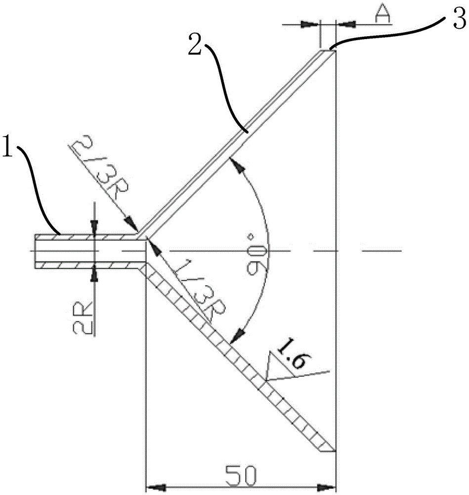
[0021] The solution of the present invention to solve the problem that the in-orbit emission plume angle of the spacecraft is less than 100° is to adopt a 45° conical protective cover with a circular arc transition, the inner surface of the protective cover is smooth, and the lip is sharp. The circular arc transition can ensure that the liquid enters the inner area of ​​the protective cover continuously and gradually. After entering the vacuum area inside the protective cover, the liquid flashes an...


PUM


Abstract

The invention provides a vacuum jet flow protective cover. The protective cover can restrain the on-track liquid drainage plume angle of a spacecraft to be less than 100 degrees. With circular arc transition, liquid jet flow can continuously enter a conical vacuum zone; turbulence and disturbance caused due to a clearance formed between the jet flow and a conical wall are avoided through a 45-degree conical angle; the flash evaporation length of 50 mm can ensure the sufficient flash evaporation of liquid, and the secondary flash evaporation of the liquid flowing out of the protective cover is avoided, and the vacuum jet flow plume angle is effectively restrained; meanwhile, the attachment of ice particles generated by flash evaporation is avoided through the smoothened inner surface and the sharpened opening of the protective cover, the profile of the protective cover is maintained complete, and the vacuum jet flow plume angle is effectively restrained.

Description

technical field [0001] The invention relates to a metal protective cover, in particular to a metal protective cover capable of effectively restricting the plume angle of a liquid vacuum jet. Background technique [0002] The on-orbit discharge of my country's spacecraft requires that the liquid outflow plume angle is less than 100° to protect the spacecraft wall and instruments near the discharge port. Commonly used measures to restrict the plume angle at home and abroad include: changing the initial temperature of the liquid, changing the outflow velocity of the liquid, and changing the diameter of the pipe. Although these measures can improve the outflow plume angle to a certain extent, they are powerless to deal with the unavoidable icing phenomenon that occurs at the orifice in the middle and later stages of discharge, because icing will change the profile of the orifice and the pipeline, resulting in The flow direction is uncontrollable and irregular, which cannot meet...

Claims


Application Information

Patent Timeline
Patent Type & Authority Patents(China)
IPC IPC(8): F02K9/52
Inventor 康亮杰江铭伟郑东晓肖开阳谌忠庭赵杨陈开莹
Owner SHANGHAI INST OF SPACE PROPULSION
Why Eureka
Try Eureka