The Method of Using Movable Reticle to Realize Datum Transformation

A technology of benchmark conversion and reticle, applied in the field of optics, can solve the problems of decreased measurement accuracy, inconvenient distinction between two graphics, inability to distinguish, etc., to ensure measurement reliability, simple conversion process, and true and reliable measurement accuracy Effect

Inactive Publication Date: 2017-04-05
苏州运昊设备制造有限公司
View PDF5 Cites 0 Cited by
  • Summary
  • Abstract
  • Description
  • Claims
  • Application Information

AI Technical Summary

Problems solved by technology

[0005] 1. Defects of the aiming method: no matter whether the alignment is observed with the CCD or the eyepiece, when the figure reflected by the external mirror coincides with the reference part, it is impossible to distinguish whether it is completely aligned, and at the same time, the two figures will interfere with each other ;like image 3 , Figure 4 Shown: When using a cross hair or dot as a reference point, when the reference itself and the reflected image do not coincide, it can be clearly carried out; Figure 5 , Image 6 Shown: Once the parts coincide, it is difficult to judge the distance between the reference and the center of the reflected figure, and it is inconvenient to distinguish between the two figures
[0006] 2. Defects in aiming reliability: If the reticle used as a reference is generated by software, the reticle generated by the software will be adjusted to the optical axis at the factory, but due to the influence of transportation, temperature changes, impacts and other factors , the crosshair used as the benchmark may deviate from the optical axis, resulting in a decrease in measurement accuracy

Method used


Image

  • The Method of Using Movable Reticle to Realize Datum Transformation
  • The Method of Using Movable Reticle to Realize Datum Transformation
  • The Method of Using Movable Reticle to Realize Datum Transformation

Examples


Embodiment 1

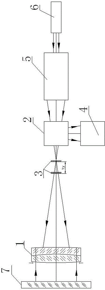
[0032] Laser autocollimators with movable reticles for fiducial conversion, e.g. figure 1 As shown, it includes a collimating objective lens 1, a spectroscopic module 2, a reticle 3, an image detection module 4, and a laser adjustment module 5. The collimating objective lens 1 is placed at the front end of the spectroscopic module 2; Between the rear end of the straight objective lens 1 and the front end of the light splitting module 2, and the reticle 3 can move back and forth along the optical axis of the collimating objective lens 1; the laser adjustment module 5 is placed at the rear end of the light splitting module 2, and the image detection module 4 is connected with the light splitting module 2.

[0033] Further, in order to better realize the laser autocollimator using a movable reticle to realize benchmark conversion according to the present invention, it also includes a laser 6, the light outlet of the laser 6 and the light inlet of the laser adjustment module 5 c...

Embodiment 2

[0038] The method for realizing benchmark conversion by using a movable reticle, using a laser autocollimator to realize benchmark conversion by using a movable reticle, comprises the following steps:

[0039] Step A, benchmark establishment: turn on the power of the laser autocollimator, start the control software, and place the reticle 3 on the convergence point of the fine alignment pattern after the beam expansion and focusing;

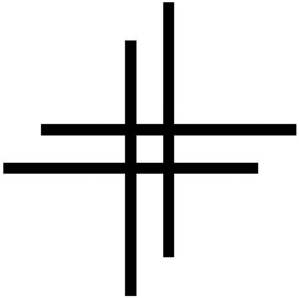
[0040] Step B. Datum conversion: the software samples the center of mass position at least twice at the convergence point of the fine alignment graph, the software calculates the average value of the centroid position and displays the datum point, and generates a crosshair as an alternative datum point, and uses this The center point of the cross hair is placed at the average position of the centroid;

[0041] Step C. Disappearance of the reference point: move the reticle axially through the control software to make the reference point disappear. ...

Embodiment 3

[0044]This embodiment is further optimized on the basis of the above-mentioned embodiments. In order to better realize the method of using a movable reticle to realize reference conversion in the present invention, the laser emitted by the laser autocollimator is reflected by the external mirror 7 , and form a bright spot through the collimating objective lens 1, the coordinates of the real-time display of this bright spot are X2 and Y2, and the distance between the alternative reference point and the reference point is D, and In the formula, L is the size of the pixel; the angle error between the external reflector and the optical axis is obtained by dividing the D value by the system focal length of the laser autocollimator.

[0045] For example, observe with CCD, if the pixel of CCD is 10um, L=10um, (X1, Y1)=(512.0, 512.0), (X2, Y2)=(572.5, 561.3), use the formula to calculate D=780.43 um, that is, the distance between the reference and the reflected image point is 780.43u...


PUM


Abstract

The invention discloses a laser autocollimator for realizing datum transformation by using a movable reticle and a method. The laser autocollimator for realizing the datum transformation by using the movable reticle comprises a collimator objective, a beam splitting module, a reticle, an image detection module and a laser adjustment module, wherein the collimator objective is arranged at the front end of the beam splitting module; the reticle is arranged between the rear end of the collimator objective and the front end of the beam splitting module; the reticle can move forward and backward along the axial direction of the collimator objective. The method comprises the steps of datum establishment, datum transformation, datum point disappearing and collimating process; in the datum transformation step, software samples the mass center positions of fine alignment graphic sinks for at least two times, calculates an average value of the mass center positions and displays a datum point; meanwhile, a reticule replacing the datum point is generated, and a center point of the reticule is arranged at the position of the average value of the mass center; in the collimating process, a datum image is enabled to disappear by a movable reticle technology, so that the interference between two images is avoided, and the problem about the distinguishing of the two images is solved.

Description

technical field [0001] The invention relates to the field of optical technology, in particular to a method for realizing benchmark conversion by using a movable reticle. Background technique [0002] Such as figure 2 As shown, the existing laser autocollimator, including collimating objective lens, light splitting module, reticle, image detection module, laser, etc., is fixedly set on the basis of quantitative optical path travel in the setting of reticle, and its work The principle is: the laser light emitted by the energy continuous laser passes through the beam splitting module and reaches the center of the reticle. This point is the focus position of the collimating objective lens, so the emitted parallel light can be reflected back to the center of the reticle by the external mirror. [0003] The light emitted by the light source is reflected by the beam splitter in the beam splitting module and illuminates the reticle located on the focal plane of the objective lens. ...

Claims


Application Information

Patent Timeline
Patent Type & Authority Patents(China)
IPC IPC(8): G01B11/26
Inventor 林亮
Owner 苏州运昊设备制造有限公司
Why Eureka
Try Eureka