Method for measuring surface tension coefficient of liquid through liquid drainage of semi-spherical shell

A liquid surface tension and liquid measurement technology, applied in the direction of surface tension analysis, etc., can solve the problems of inaccurate measurement of liquid column height, low measurement accuracy, and difficult coordinate values, and achieve a simple structure, low cost, and high cost Effect

Inactive Publication Date: 2015-03-11
SICHUAN UNIV
View PDF4 Cites 2 Cited by
  • Summary
  • Abstract
  • Description
  • Claims
  • Application Information

AI Technical Summary

Problems solved by technology

[0002] Common methods for measuring the surface tension coefficient of liquids are: maximum bubble pressure method, capillary method, pull-off method, etc. The measurement method is either complicated, such as the maximum bubble pressure method, pull-off method; or the measurement accuracy is not high, although the capillary method is simple , but the liquid surface is curved, and the height of the liquid column is not accurate enough. Since the liquid surface outside the capillary also rises along the tube wall outside the capillary, it is difficult to determine the coordinate value of the horizontal position of the liquid surface, which leads to the determination of the inside of the capillary. The height difference of the liquid column is more difficult

Method used


Image

  • Method for measuring surface tension coefficient of liquid through liquid drainage of semi-spherical shell
  • Method for measuring surface tension coefficient of liquid through liquid drainage of semi-spherical shell
  • Method for measuring surface tension coefficient of liquid through liquid drainage of semi-spherical shell

Examples


Embodiment Construction

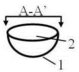
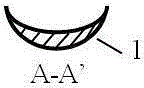
[0008] A hemispherical shell 1, the radius of the outer spherical shell is R, because it is a hemispherical shell, that is, the outer radius of the circle where the opening 2 of the hemispherical shell is located is R, the bottom of the hemispherical shell 1 is thick and the upper end is thin, and the deformation occurs inside the hemispherical shell , the outside is a standard spherical shape, such as figure 2 As shown, that is, its center of gravity shifts to the bottom of the hemispherical shell 1; the average density of the hemispherical shell 1 is the mass m of the hemispherical shell 1 and the volume of the spherical gap (hemispherical volume) enclosed by the outside of the hemispherical shell 1 is 2πR 3 / 3 divided, average density=m / (2πR 3 / 3), the average density of the hemispherical shell 1 is less than the density of the liquid, and the optimal value is 0.5-0.8 times the liquid density, because the liquid density changes greatly with the temperature change, and the ...


PUM


Abstract

The invention relates to the measurement of physical parameters, in particular to a method for measuring the surface tension coefficient of a liquid through liquid drainage of a semi-spherical shell. The method adopts the technical scheme that the spherical shell outside radius of the semi-spherical shell is R, and the average density of the semi-spherical shell is 0.5 to 0.8 time of the liquid density; the liquid is injected into an overflow trough until the liquid overflows to a cup at the lower end of a guide trench through the guide trench at the upper edge of the overflow trough; when the liquid stops dripping at the tail end of the guide trench, the mass m1 of the cup is measured, and the cup is then placed right below the tail end of the guide trench; the mass m of the semi-spherical shell is measured; the semi-spherical shell is slowly placed into the overflow trough in a manner that the opening of the semi-spherical shell is upward, the liquid flows into the cup at the tail end of the guide trench, the mass m2 of the cup accommodating the liquid is measured when no liquid drips at the tail end of the guide trench, and the liquid surface tension is [m-(m2-m1)] * g; the surface tension coefficient of the liquid sigma=[m-(m2-m1)]*g / (2*pi*R2), and R2 is the radius of the contact circle of the liquid level and the spherical shell. The method has the benefits of being simple in structure, low in cost and easy in operation.

Description

technical field [0001] The invention relates to the measurement of physical parameters, especially the measurement of the surface tension coefficient of liquids. Background technique [0002] Common methods for measuring the surface tension coefficient of liquids are: maximum bubble pressure method, capillary method, pull-off method, etc. The measurement methods are either relatively complicated, such as the maximum bubble pressure method, pull-off method; or the measurement accuracy is not high, although the capillary method is simple , but the liquid surface is curved, and the height of the liquid column is not accurate enough. Since the liquid surface outside the capillary also rises along the tube wall outside the capillary, it is difficult to determine the coordinate value of the horizontal position of the liquid surface, which leads to the determination of the inside of the capillary. The height difference of the liquid column is more difficult. Contents of the inven...

Claims


Application Information

Patent Timeline
IPC IPC(8): G01N13/02
Inventor 李娟胡再国饶大庆雍志华罗明蓉穆万军邹旭敏王维果梁雅庭程艳刘石丹于白茹李伟梁小冲李紫源田野中朱俊何原
Owner SICHUAN UNIV
Why Eureka
Try Eureka