
Transformer suitable for switch power supply

A switching power supply and transformer technology, applied in the field of transformers, can solve problems such as power reduction, poor contact, and reactance reduction, and achieve the effects of avoiding power reduction, avoiding varnish damage, and enhancing stability.

Inactive Publication Date: 2015-03-11
MIANYANG RONGFU ELECTRONICS TECH
View PDF6 Cites 2 Cited by
  • Summary
  • Abstract
  • Description
  • Claims
  • Application Information

AI Technical Summary

Problems solved by technology

However, this structure will have problems during use, that is, it is necessary to ensure that the positions of the I stack and the E stack are fixed. Since the I stack and the E stack are in contact, it is prone to problems, that is, the I stack and the E stack are in contact with each other. The position of the laminations is prone to shift, which makes the contact between the two poor. Similar to the reduction of the iron core, the reactance is reduced, and the power is also reduced. In severe cases, the coil may even heat up or burn out.

Method used


Image

  • Transformer suitable for switch power supply
  • Transformer suitable for switch power supply

Examples


Embodiment 1

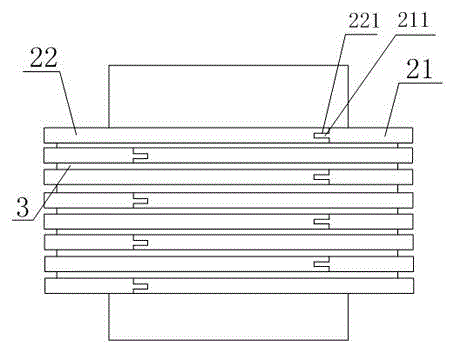
[0020] Such as figure 1 and figure 2 The shown transformer suitable for switching power supplies includes an iron core element, the iron core element includes a plurality of parallel flat laminations stacked together, the laminations include an anti-slip layer 3, the The anti-skid layer 3 is provided with a plurality of holes, and the lamination includes an E lamination 21 and a second lamination 22, and the E lamination 21 and the second lamination 22 are put together to form a "day" shape, so A groove 211 is provided on the contact surface of the E laminate 21 and the second laminate 22 , and a block 221 matching the groove 211 is provided on the second laminate 22 .

Embodiment 2

[0022] Such as figure 1 and figure 2 In the shown transformer suitable for switching power supplies, this embodiment specifically discloses the structure of the second lamination on the basis of the above-mentioned embodiment, that is, the section of the second lamination 22 is "E"-shaped .

Embodiment 3

[0024] Such as figure 1 and figure 2 In the shown transformer suitable for switching power supplies, this embodiment specifically discloses the structure of the second lamination on the basis of the above embodiment, that is, the section of the second lamination 22 is "I"-shaped .


PUM

PropertyMeasurementUnit
Depthaaaaaaaaaa
Depthaaaaaaaaaa

Abstract

The invention discloses a transformer suitable for a switch power supply, and the transformer comprises an iron core element which comprises a plurality of flat laminations in parallel stacked together, wherein the lamination comprises an anti-skidding layer on which a plurality of holes are arranged, the lamination comprises an E-shaped lamination and a second lamination both which are together formed into the shape of the Chinese character 'sun', the contact surfaces of the E-shaped lamination and the second lamination are respectively provided with a groove, the second lamination is provided with a fixture block matching the groove, and the transformer has the advantages of steady iron core element structure and reliable lamination contact, thus the transformer isn't easy to displace, and the phenomenon of power reduction and coil heating can be avoided in use.

Description

[0001] technical field [0002] The invention relates to a transformer suitable for switching power supplies. Background technique [0003] The transformer uses the principle of mutual inductance to change the AC voltage and consists of a primary coil, a secondary coil and an iron core. The structure of the existing transformer core includes a plurality of laminations, and the laminations include lamination elements with sections "I" and "E", and the I laminations and the E laminations form a "day"-shaped lamination. The center arm of the E-stack sits in the center of the spool. Since the laminations are stacked one by one, that is, after the I laminations of the first layer and the E laminations are butted, the laminations of the second layer are assembled on the core element in the opposite direction, that is, the upper and lower adjacent laminations of the I laminations are all E stack. However, this structure will have problems during use, that is, it is necessary to ...

Claims


Application Information

Patent Timeline
IPC IPC(8): H01F27/26H01F27/245
Inventor 林中金田仁模
Owner MIANYANG RONGFU ELECTRONICS TECH
Learn More