Paralleled current sharing control method of photovoltaic inverter

A photovoltaic inverter and flow control technology, applied in the direction of photovoltaic power generation, AC power input conversion to DC power output, output power conversion devices, etc., can solve problems such as not suitable for photovoltaic systems and cannot work normally, and achieve good dynamics and steady-state performance, avoiding cost increases, and avoiding large system volume increases

Inactive Publication Date: 2015-03-11
SINENG ELECTRIC CO LTD
View PDF10 Cites 7 Cited by
  • Summary
  • Abstract
  • Description
  • Claims
  • Application Information

AI Technical Summary

Problems solved by technology

However, this method will not work properly when the current sharing bus is short-circuited or the power unit is not working
Other current sharing control methods include external characteristic droop method, active and reactive power method, etc. However, these methods are all aimed at parallel connection of voltage sources, and have their own limitations, so they are not suitable for direct application to photovoltaic systems.

Method used


Image

  • Paralleled current sharing control method of photovoltaic inverter
  • Paralleled current sharing control method of photovoltaic inverter

Examples


Embodiment 1

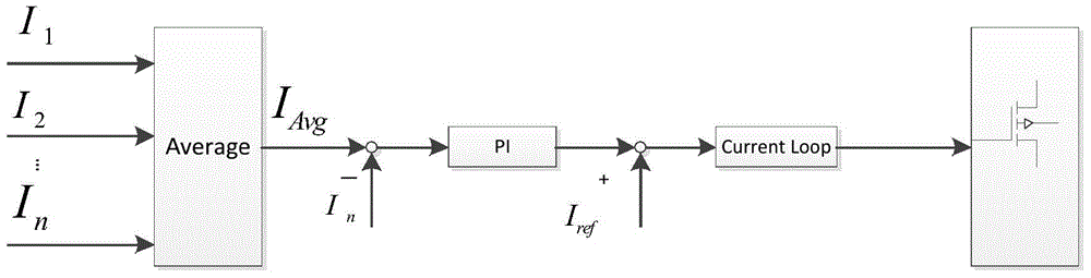
[0016] In this embodiment, the parallel current sharing control method of photovoltaic inverters specifically includes the following steps:

[0017] S101. Each power unit constituting the photovoltaic inverter sends the active component and the reactive component of the output current to other power units through CAN communication.

[0018] During specific implementation, each power unit constituting the photovoltaic inverter rotates and transforms the instantaneous current value to obtain active and reactive components of the D-axis and Q-axis, and sends the active and reactive components to other power units.

[0019] S102. The power unit calculates the received current information sent by other power units and its own current information to obtain an average current. The current information includes an active component and a reactive component of the output current.

[0020] S103, adjusting the output current through the current equalization regulator to realize current equ...

Embodiment 2

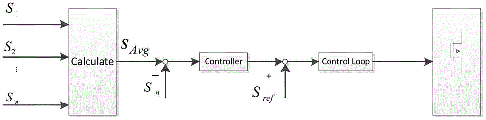
[0024] Such as figure 2 Shown, S 1 …S n It is a variable related to the output current. In the embodiment, the variable is instantaneous power, and Calculate represents the load distribution calculation of each power unit (the specific process is the same as the method in Embodiment 1, and will not be repeated here), S Avg is the average value of the output power of each power unit, S ref For power reference, Controller can be any one of closed-loop PI regulator, hysteresis regulator or other regulators, and Control loop represents the single-loop or double-loop regulation unit of the control object. In this embodiment, the instantaneous power is used to realize precise load distribution and regulation of each power unit.

[0025] The technical solution of the present invention has the following advantages: 1. The instantaneous value of the current is controlled through the rotation transformation, and compared with the traditional method of using the effective value for c...


PUM


Abstract

The invention discloses a paralleled current sharing control method of a photovoltaic inverter. By the method, a current momentary value is controlled in a rotation transformation manner. Compared with the traditional method by which current sharing is carried out on the basis of effective values, the paralleled current sharing control method is high in dynamic response speed. A closed-loop current sharing adjusting mode is used, the dynamic performance and the steady-state performance are high; after current sharing is performed on the photovoltaic inverter, ring current of a system is reduced obviously, and the system can run stably and reliably; extra hardware is not required, fault points are reduced, and the cost and the size of the system are prevented from being increased; and an adjusting mode is flexible, and load distribution of various power units can be adjusted flexibly as needed.

Description

technical field [0001] The invention relates to the technical field of photovoltaic inverters, in particular to a parallel current sharing control method for photovoltaic inverters. Background technique [0002] Using multiple power units in parallel to realize high-power photovoltaic inverters is the development direction of photovoltaic inverters in the future, and the key to paralleling multiple power units is to share the load among each power unit. At present, there are few researches on the parallel connection of photovoltaic inverters, and the research is generally on the parallel current sharing technology of voltage sources. There are mainly the following methods for voltage source parallel connection current sharing: 1. Current limiting inductance method: This method is simple and easy to implement. However, the hardware cost is increased, which is not good for improving the system efficiency, and in order to take into account the dynamic and steady-state performa...

Claims


Application Information

Patent Timeline
Patent Type & Authority Applications(China)
IPC IPC(8): H02M7/493
CPCY02E10/56H02M7/493
Inventor 邓福伟葛鹏霄陈保群蔡子海
Owner SINENG ELECTRIC CO LTD
Why Eureka
Try Eureka