
Improved video shot detection method

A lens detection and lens technology, applied in special data processing applications, instruments, electrical and digital data processing, etc., can solve the problems of wrong detection of lens boundaries, interference with lens detection effects, and difficulty in obtaining effects, so as to improve the detection degree and accuracy. degree of effect

Inactive Publication Date: 2015-03-11
BEIJING JINGDONG SHANGKE INFORMATION TECH CO LTD +1
View PDF5 Cites 9 Cited by
  • Summary
  • Abstract
  • Description
  • Claims
  • Application Information

AI Technical Summary

Problems solved by technology

It is difficult to obtain better results by applying a certain method or a certain low-level visual feature of the video alone to detect the video shot
[0011] For the pixel-based method, although the algorithm is simple and easy to implement, it is very sensitive to the movement of the object / camera in the lens. The movement of the object / camera in the lens will cause the grayscale or brightness of most pixels in the image frame to change, thus Causes false detection of shot boundaries; for the histogram-based method, since the histogram cannot reflect the position information and visual content of the image, two images with unrelated content may also have the same grayscale / color overall distribution, with the same color The two images of the overall distribution may also have the same object and background, but the position of the object is different, which may lead to false detection of the lens boundary; in addition, the situation of severe lighting changes (such as flashes, etc.) Interfering with the lens detection effect of the above two methods

Method used


Image

  • Improved video shot detection method
  • Improved video shot detection method

Examples


Embodiment Construction

[0024] An improved video shot detection method is disclosed according to an embodiment of the present invention. In the following description, for purposes of explanation, numerous specific details are set forth in order to provide a thorough understanding of embodiments of the invention. It will be apparent, however, to one skilled in the art that embodiments of the invention may be practiced without these specific details.

[0025] The structure of video can generally be divided into four levels: video sequence, scene, shot and frame. Specifically, a video sequence refers to a single frame of video file, or a frame of video clips. A video sequence consists of several scenes. Each scene consists of one or more shots, which can be continuous or spaced. Each shot contains several consecutive image frames. A scene is a video clip composed of several semantically related shots that can express certain semantic content. These voice-related shots can be continuous or intermitte...


PUM


Abstract

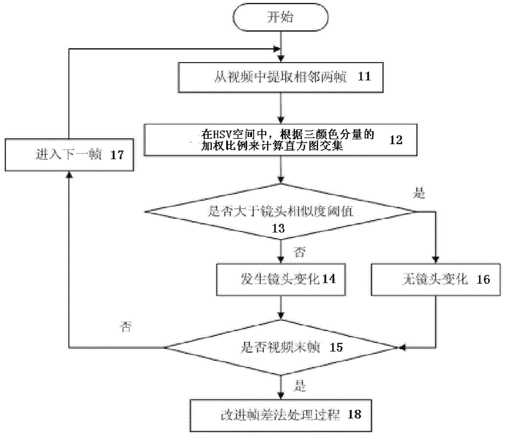
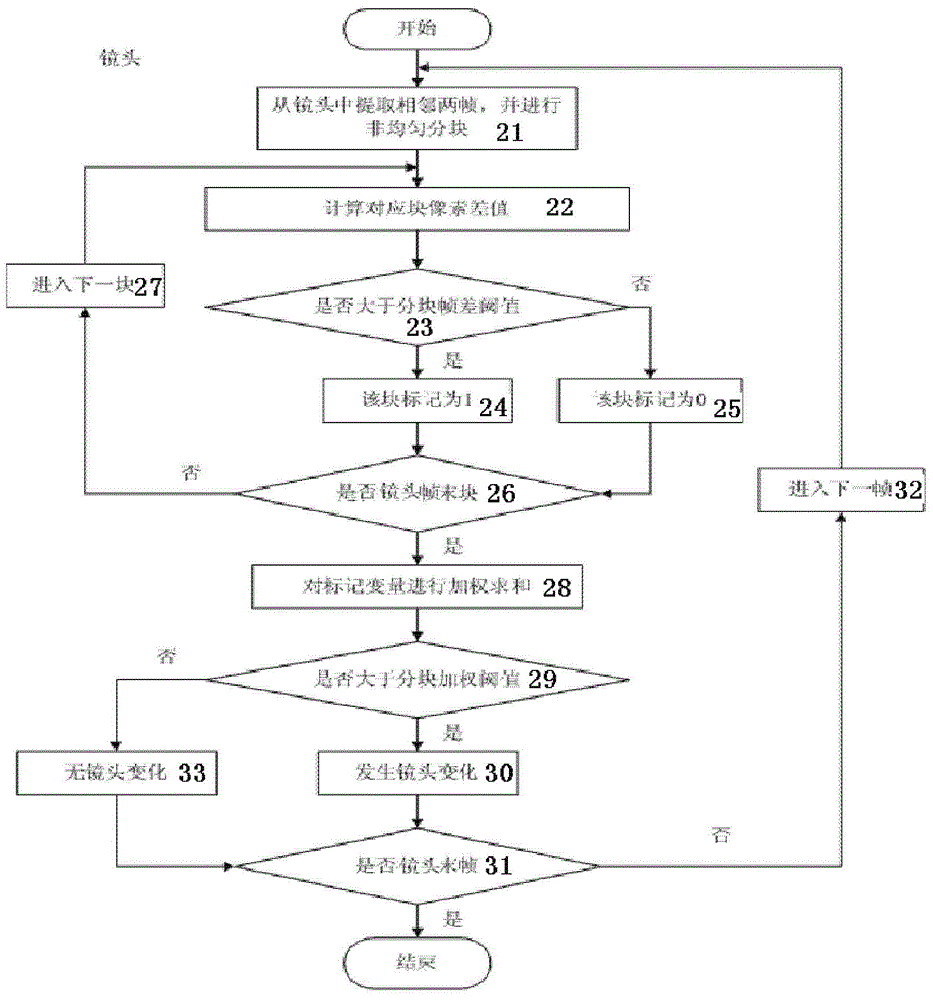
The invention discloses a video shot detection method. The detection method comprises the following steps: histogram method processing procedure which comprises the following steps: extracting two adjacent frames from the video, computing histogram intersection according to weighting proportion of three color components in a HSV space; and judging whether the shot change occurs; frame difference method processing procedure, if judging that the shot change occurs, entering the frame difference method processing procedure, wherein the frame difference method processing procedure further comprises the following steps: extracting two adjacent frames from the shot and performing non-uniform blocking; computing pixel difference value of each of the blocks; comparing the pixel difference value with a predetermined block frame difference threshold value so as to perform sign; performing weighting summation on the sign variables in the blocks; comparing the summation with a set block weighting threshold value, if the summation is greater than the block weighting threshold value, regarding that the shot change occurs.

Description

technical field [0001] The present invention relates to video shot segmentation technology, and more particularly, the present invention relates to an improved video shot detection method. Background technique [0002] With the increasing abundance of video data at this stage, how to effectively organize, manage, query and retrieve the massive video information on the Internet, and find the video clips that users are interested in, has become more and more urgent. Video shot segmentation technology is one of the core issues of content-based video retrieval, which can be effectively used to manage the large amount of disordered video data on the Internet. Through this technology and key frame extraction technology to structure the video and create an index and summary for the video, only when the linear structure of the video content is formed, can the fast browsing and retrieval of video data be effectively realized. [0003] At present, the common method of video shot dete...

Claims


Application Information

Patent Timeline
IPC IPC(8): H04N21/234H04N21/44G06F17/30
CPCG06F16/783G06V20/49
Inventor 高腾飞
Owner BEIJING JINGDONG SHANGKE INFORMATION TECH CO LTD
Learn More