Device for supplying power supply loop for control unit

A technology of control unit and rectifier circuit, which is applied in the direction of lamp circuit layout, lighting device, electric light source, etc., and can solve the problems of inconvenient use, long wiring 12, increased cost, etc.

Active Publication Date: 2015-03-11
HANGZHOU SILAN MICROELECTRONICS
View PDF2 Cites 4 Cited by
  • Summary
  • Abstract
  • Description
  • Claims
  • Application Information

AI Technical Summary

Problems solved by technology

At present, in practical applications, the power supply of the dimmer or control panel is generally supplied in two ways: the first way is to directly install dry batteries in the dimmer or control panel. In this way, the battery needs to be replaced frequently, which is inconvenient to use and high in cost. ; figure 1 As shown, in the loop

Method used


Image

  • Device for supplying power supply loop for control unit
  • Device for supplying power supply loop for control unit
  • Device for supplying power supply loop for control unit

Examples


no. 1 example

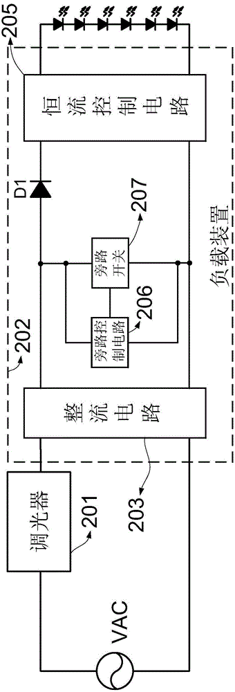
[0056] refer to figure 2 , figure 2 A schematic circuit diagram of the device for providing a power supply circuit for the control unit of the first embodiment is given. The device mainly includes: an AC input power supply VAC, a control unit 201 and a load device (or called a driving power supply) 202 . Wherein, the load device 202 includes a rectification circuit 203 , a bypass control circuit 206 , a bypass switch 207 , a diode D1 and a constant current control circuit 205 . The output end of the bypass device is connected to a load, such as an LED lamp bead.

[0057] The control unit 201 may be a dimmer in this embodiment, but it is not limited thereto, for example, it may also be a control panel for controlling lamps and the like.

[0058] The AC signal output by the AC input power supply VAC is transmitted to the first input terminal of the rectification circuit 203 through the control unit 201 , and the rectification circuit 203 rectifies the output signal of the c...

no. 2 example

[0066] refer to image 3 , Figure 4 and Figure 6 , image 3 A schematic circuit diagram of the device for providing a power supply circuit for the control unit of the second embodiment is given, Figure 4 gives image 3 The equivalent circuit diagram when the switch tube Q1 is turned on, Figure 6 A schematic diagram of the main working waveforms of the second embodiment is given.

[0067] In the second embodiment, the bypass switch includes a switch tube Q1, the first end of which is connected to the first output end of the rectification circuit 203, and the second end thereof is connected to the second output end of the rectification circuit 203 via the first resistor R1.

[0068] The switch tube Q1 can be a MOSFET transistor, the first terminal of the switch tube Q1 is the drain of the MOSFET transistor, the second terminal of the switch tube Q1 is the source of the MOSFET transistor, and the control terminal of the switch tube Q1 is the gate of the MOSFET transistor...

no. 3 example

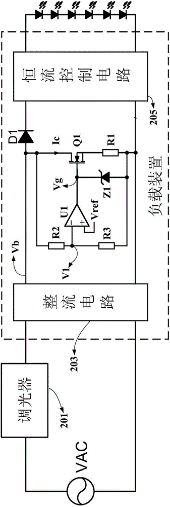
[0084] refer to Figure 5 , Figure 5 A schematic circuit diagram of the device for providing a power supply circuit for the control unit of the third embodiment is given. The difference between this embodiment and the second embodiment is that the bypass control circuit detects the input signal of the rectification circuit 203 . Specifically, the voltage dividing network composed of the second resistor R2 and the third resistor R3 is set at the input end of the rectification circuit 203 , and divides the signal at the input end of the rectification circuit 203 to obtain the detection voltage. The inverting input terminal of the comparator U1 receives the detection voltage obtained by voltage division, and the non-inverting input terminal of the comparator U1 receives the reference voltage Vref.

[0085] The working principle of the third embodiment is the same as that of the second embodiment, and will not be repeated here.


PUM


Abstract

The invention provides a device for supplying a power supply loop for a control unit. The device comprises an alternating current input power, the control unit and a loading device, wherein the input end of the control unit is connected with an alternating current first end; the loading device comprises a rectifying circuit, a bypass control circuit and a by-pass switch, and the rectifying circuit is used for rectifying an output signal of the control unit; the bypass control circuit is used for detecting an electric signal in the loading device to generate detection voltage and generating a bypass switch control signal according to the detection voltage; when the by-pass switch responding to the bypass switch control signal is effective, the by-pass switch is switched on, so that the alternating current input power, the control unit and the by-pass switch can form a conducting loop; when the by-pass switch responding to the bypass switch control signal is noneffective, the by-pass switch is switched off, so that the conducting loop is disconnected. The third port of the control unit and an additional conducting wire are not needed, so that the device is beneficial to simplification of the circuits, reduction of the complexity degree of practical engineering construction, and reduction of the cost.

Description

technical field [0001] The invention relates to the power supply technology of a control unit, in particular to a device for providing a power supply circuit for the control unit. Background technique [0002] Lighting systems usually include systems such as general household lighting, commercial lighting, road lighting and landscape lighting. At present, the lighting system of most households in China simply uses a switch to control the on and off of the light, that is, the light has only two states, either on or off. In foreign countries, especially in North American countries, household lighting involves dimming function, that is, the brightness and color of lights can be changed through control units (such as dimmers or control panels) to achieve a certain comfort level. For example, hotels, conference rooms, shopping malls and other occasions often need to control and adjust the lighting. At present, the usual adjustment method is to adjust the brightness of the light...

Claims


Application Information

Patent Timeline
IPC IPC(8): H05B37/02
Inventor 蔡拥军叶美盼
Owner HANGZHOU SILAN MICROELECTRONICS
Why Eureka
Try Eureka