Droplet cutting method and droplet cross-section analysis method

A technology of cutting method and analysis method, applied in the direction of analysis materials, preparation of test samples, instruments, etc., can solve problems such as unrealization and difficulty in cross-section exposure

Inactive Publication Date: 2015-03-11
NITTO DENKO CORP
View PDF5 Cites 2 Cited by
  • Summary
  • Abstract
  • Description
  • Claims
  • Application Information

AI Technical Summary

Problems solved by technology

[0007] However, it is very difficult to expose the cross-section of a liquid sample whose main component is a low-viscosity liquid component, such as an emulsion, in a state where the structure is fixed in the existing FIB processing technology.
In particular, when exposing the cross section of such a liquid sample, it is necessary to fix the structure in the droplet state, but it has not been possible to perform FIB processing after the droplet is sufficiently fixed.

Method used


Image

  • Droplet cutting method and droplet cross-section analysis method
  • Droplet cutting method and droplet cross-section analysis method
  • Droplet cutting method and droplet cross-section analysis method

Examples


Embodiment 1

[0107] Using a sputtering device (manufactured by ULVAC, RFS-200), an Al thin film (thickness 5 nm) was formed on a silicon wafer (manufactured by Silicon Technology Co., Ltd.) as a substrate. A sputtering device (manufactured by ULVAC, RFS-200) was used to deposit an Fe thin film (thickness 0.35 nm) on the Al thin film.

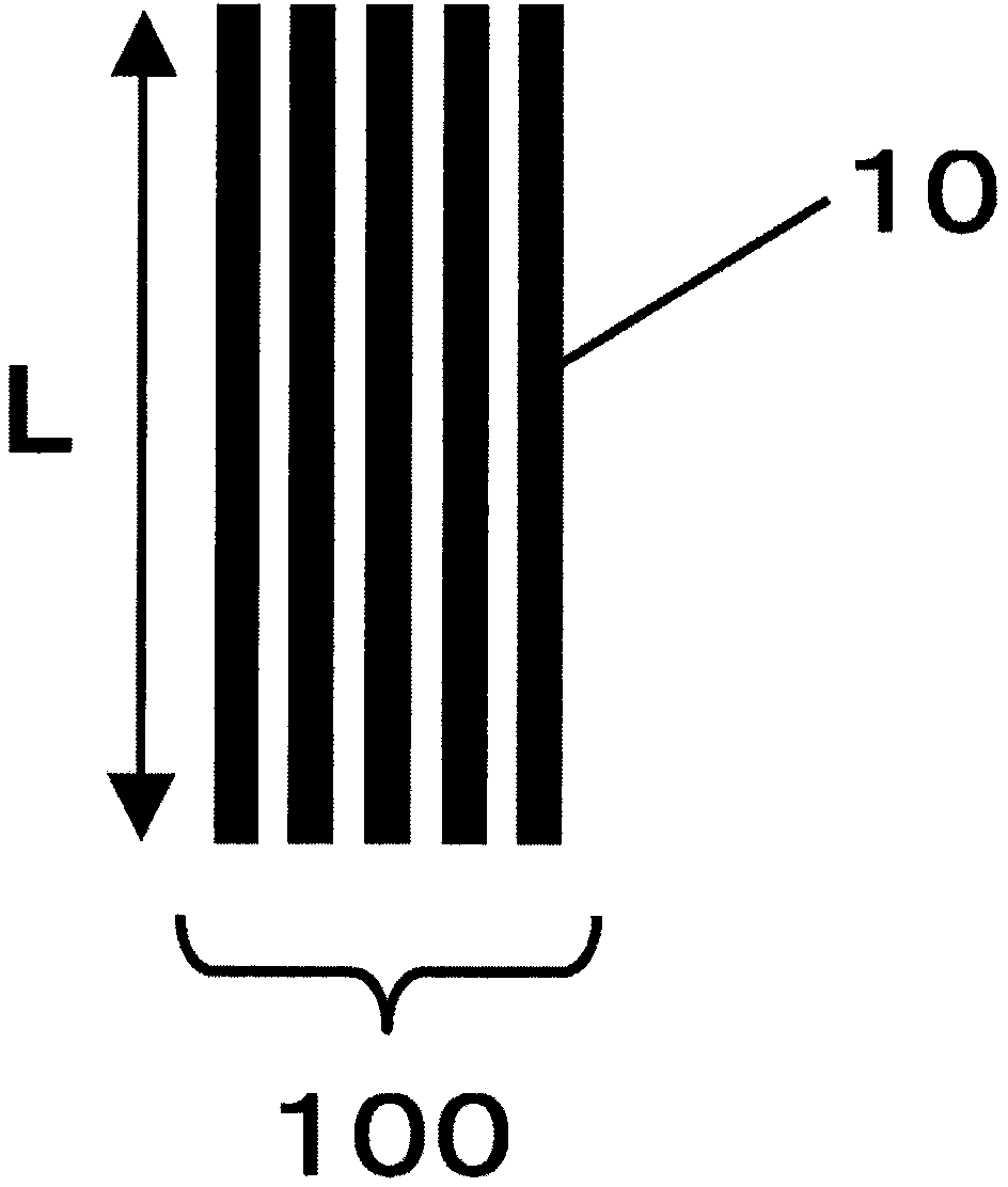
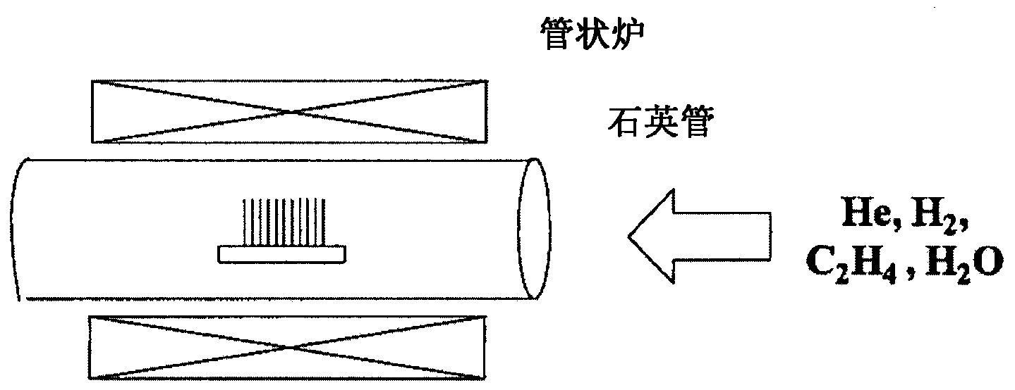
[0108] After that, place the substrate In the quartz tube, circulate a helium / hydrogen (90 / 50sccm) mixed gas that holds 600 ppm of moisture into the quartz tube for 30 minutes to replace the inside of the tube. After that, a tubular electric furnace was used to raise the temperature in the tube to 765°C and stabilize it at 765°C. Keep the temperature at 765℃, fill the tube with helium / hydrogen / ethylene (85 / 50 / 5sccm, moisture content 600ppm) mixed gas, and leave it for 4 minutes to grow carbon nanotubes on the substrate to obtain carbon nanotubes in the length direction Up-oriented carbon nanotube assembly (1).

[0109] The length of the carbon nanotube aggrega...

Embodiment 2

[0115] Using a sputtering device (manufactured by ULVAC, RFS-200), an aluminum oxide film (thickness 20 nm) was formed on a silicon wafer (manufactured by Silicon Technology Co., Ltd.) as a substrate. A sputtering device (manufactured by ULVAC, RFS-200) was used to deposit an Fe thin film (thickness: 1 nm) on the aluminum oxide thin film.

[0116] After that, place the substrate In the quartz tube, circulate a helium / hydrogen (90 / 50sccm) mixed gas that holds 600 ppm of moisture into the quartz tube for 30 minutes to replace the inside of the tube. After that, a tubular electric furnace was used to raise the temperature in the tube to 765°C and stabilize it at 765°C. Keep the temperature at 765℃, fill the tube with helium / hydrogen / ethylene (85 / 50 / 5sccm, moisture content 600ppm) mixed gas, and leave it for 10 minutes to grow carbon nanotubes on the substrate to obtain carbon nanotubes in the length direction Up-oriented carbon nanotube assembly (2).

[0117] The length of the carb...

Embodiment 3

[0122] Using a sputtering device (manufactured by ULVAC, RFS-200), an Al film (thickness 5 nm) was formed on a silicon wafer (manufactured by Silicon Technology Co., Ltd.) as a substrate. A sputtering device (manufactured by ULVAC, RFS-200) was used to deposit an Fe thin film (thickness 2 nm) on the Al thin film.

[0123] After that, place the substrate In the quartz tube, circulate a helium / hydrogen (90 / 50sccm) mixed gas that holds 600 ppm of moisture into the quartz tube for 30 minutes to replace the inside of the tube. After that, a tubular electric furnace was used to raise the temperature in the tube to 765°C and stabilize it at 765°C. Keep the temperature at 765℃, fill the tube with helium / hydrogen / ethylene (85 / 50 / 5sccm, moisture content 600ppm) mixed gas, and leave it for 20 minutes to grow carbon nanotubes on the substrate to obtain carbon nanotubes in the length direction Up-oriented carbon nanotube assembly (3).

[0124] The length of the carbon nanotube aggregate (3) ...


PUM

PropertyMeasurementUnit
lengthaaaaaaaaaa
lengthaaaaaaaaaa
lengthaaaaaaaaaa

Abstract

Provided is a droplet cutting method whereby droplets can be readily cut and the cross-sections thereof exposed. Also provided is a droplet cross-section analysis method whereby cross-sections cut and exposed using this kind of cutting method are analyzed. This droplet cutting method is a method for cutting droplets and exposing the cross-sections thereof. Droplets are placed on the surface of a carbon nanotube aggregate comprising a plurality of carbon nanotubes, cooled to cooling temperature of no more than a temperature at which the droplets solidify, and cut. This droplet cross-section analysis method is used to analyze cross-sections cut and exposed using this droplet cutting method.

Description

Technical field [0001] The invention relates to a method for cutting liquid droplets. Specifically, it relates to a cutting method capable of easily cutting liquid droplets and exposing the cross-section of liquid droplets. The present invention also relates to an analysis method of a droplet cross section for analyzing a cross section exposed by cutting by such a cutting method. Background technique [0002] In recent years, with the miniaturization of various products and materials, nano-level structure control is required. Therefore, nanoscale structural analysis is required. [0003] In particular, recently, as a nano-level structure control, not only the control of the surface structure, but also the control of the internal structure in most cases. Therefore, as a nano-level structural analysis, it is not only necessary to analyze the surface structure, but also to analyze the internal structure. [0004] In order to analyze the internal structure of a fine sample, the cross...

Claims


Application Information

Patent Timeline
Patent Type & Authority Applications(China)
IPC IPC(8): G01N1/06G01N1/28
CPCG01N1/04G01N1/42Y10T83/041G01N1/06G01N1/28H01J37/31B26D7/08G01N1/286G01N2001/2873H01J37/32321H01J2237/31749
Inventor 前野洋平
Owner NITTO DENKO CORP
Why Eureka
Try Eureka