Optical fiber connector, method for manufacturing optical fiber connector, method for connecting optical fiber connector and optical fiber, and assembled body of optical fiber connector and optical fiber

A technology of optical fiber connector and optical fiber, applied in the direction of optical waveguide light guide, coupling of optical waveguide, light guide, etc., can solve the problems of complexity, light loss, and many processes, and achieve the effect of not being easy to shift position

Inactive Publication Date: 2015-03-11
RESONAC CORPORATION
View PDF8 Cites 15 Cited by
  • Summary
  • Abstract
  • Description
  • Claims
  • Application Information

AI Technical Summary

Problems solved by technology

[0005] However, in such an optical fiber connector, it is necessary to cut the optical fiber mounting groove by dicing, so the work efficiency is poor. In addition, the optical waveguide core is produced by photolithography and etching in a process other than the groove cutting process, so sometimes The positional deviation of the fiber will occur
Furthermore, in the above method, if it is not formed on a hard substrate with good dimensional stability such as a silicon wafer, the optical fiber will have a greater positional deviation.
[0006] In addition, there is a method of connecting an optical fiber and an optical waveguide in which a waveguide substrate on which an optical waveguide is formed and an optical connector with an optical fiber are mounted on different holders and the end faces of the holders are adhered to each other as described in Patent Document 3. However, the number of processes to complete the connection is large and complicated
[0007] In addition, regarding the optical fiber connector described in Patent Document 4 in which an optical fiber mounting groove and an optical waveguide are arranged side by side, an optical fiber fixing adhesive and an optical fiber are introduced into the optical fiber mounting groove and pressed from the fiber mounting side with a fixing jig, Align the optical waveguide and the optical fiber, but there is the following problem: If the fixing jig is not kept horizontal when the optical fiber is fixed, the axis of the optical fiber and the optical waveguide will shift, resulting in light loss

Method used


Image

  • Optical fiber connector, method for manufacturing optical fiber connector, method for connecting optical fiber connector and optical fiber, and assembled body of optical fiber connector and optical fiber
  • Optical fiber connector, method for manufacturing optical fiber connector, method for connecting optical fiber connector and optical fiber, and assembled body of optical fiber connector and optical fiber
  • Optical fiber connector, method for manufacturing optical fiber connector, method for connecting optical fiber connector and optical fiber, and assembled body of optical fiber connector and optical fiber

Examples


no. 1 Embodiment approach

[0086] (Structure of fiber optic connector)

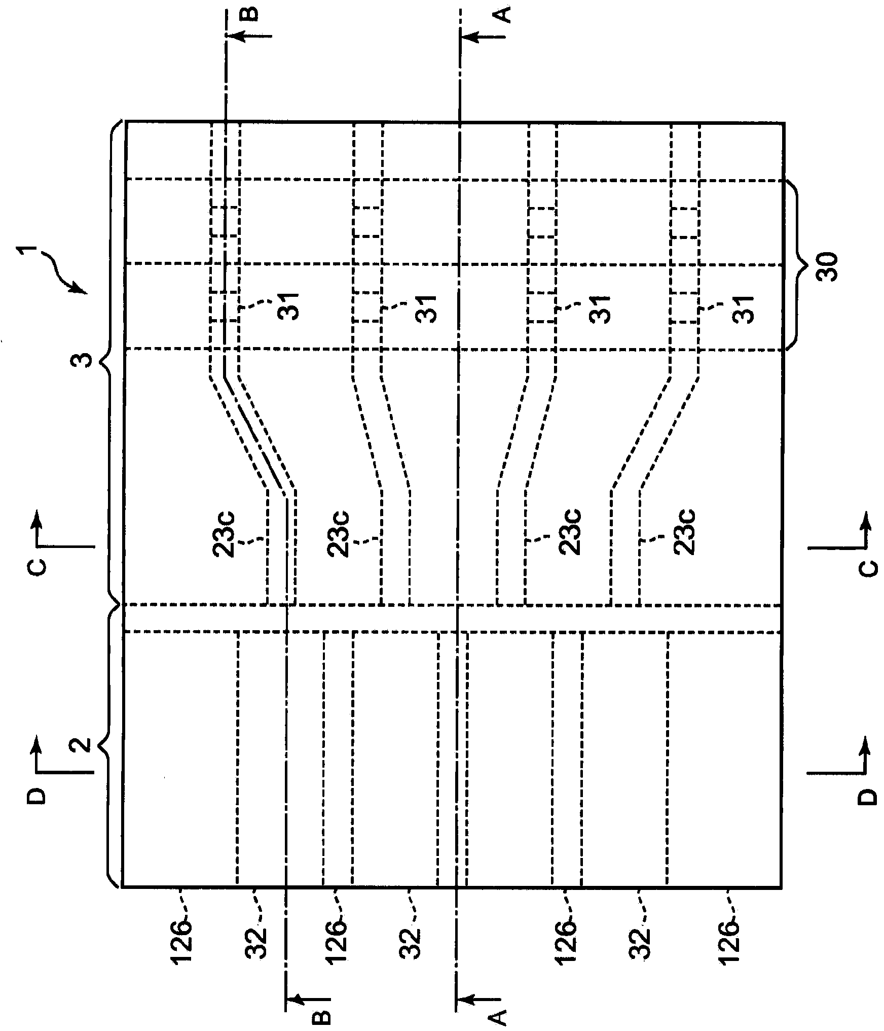
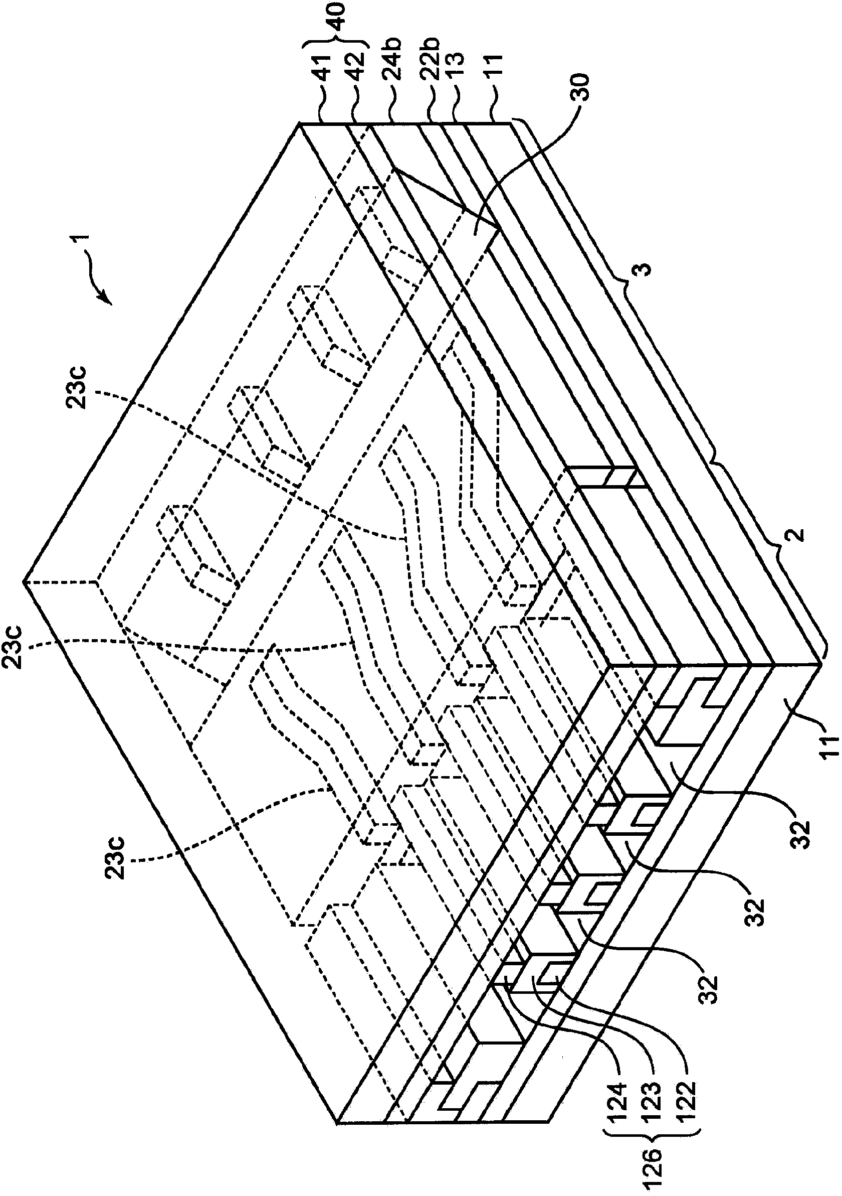
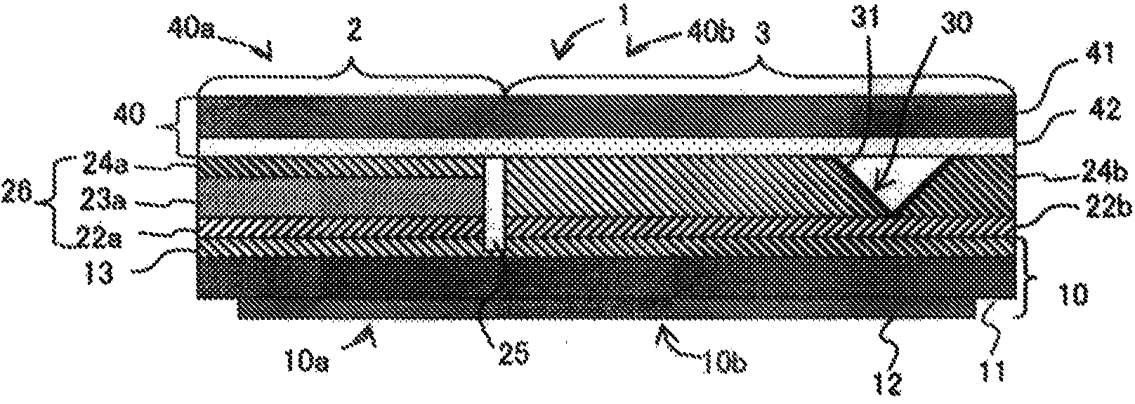
[0087] Hereinafter, the optical fiber connector 1 according to the first embodiment will be described with reference to the drawings. figure 1 It is a plan view showing the optical fiber connector 1 of the first embodiment, figure 2 It is a perspective view showing the optical fiber connector of the first embodiment, image 3 for along figure 1 The end view of the A-A line, Figure 4 for along figure 1 The end view of the B-B line, Figure 5 for along figure 1 The end view of the C-C line, Figure 6 for along figure 1 End view of the D-D line.

[0088] The optical fiber connector 1 of the first embodiment is an optical fiber connector in which an optical fiber guide member 2 and an optical waveguide 3 are arranged side by side.

[0089] The fiber guide member 2 is composed of a part constituting the substrate 10 ( image 3 The fiber guide side substrate part 10a on the left side in the middle), the fiber guide pattern 26...

no. 2 Embodiment approach

[0191] (Structure of fiber optic connector)

[0192] In the optical fiber connector of the second embodiment, in the optical fiber connector of the first embodiment, instead of the slit groove 25 or together with the slit groove 25, there is an adhesive introduction that communicates with the outside of the optical fiber guide member 2 and the fiber guide groove 32. Slit fiber optic connectors.

[0193] In the optical fiber connector of the second embodiment, the fiber guide groove 32 communicates with the outside through the fiber insertion port of the fiber guide groove 32 and communicates with the outside through the adhesive introduction slit. Therefore, when the adhesive is introduced from one of the optical fiber insertion port and the adhesive introduction slit, the air in the fiber guide groove 32 flows out from the other of the optical fiber insertion port and the adhesive introduction slit. Thus, the adhesive can be easily introduced into the fiber guide groove 32 ....

Embodiment 1

[0279] [Production of Optical Fiber Connector 1A]

[0280] (1st process)

[0281] The 20 μm thick lower cladding layer-forming resin film obtained above was cut into a size of 100×100 μm, the protective film was peeled off, and laminated on the second lower cladding layer side by a vacuum laminator under the same conditions as above. Irradiate 250mJ / cm from the carrier film side through a negative photomask with 95μm x 3.0mm x 4 non-exposed parts using an ultraviolet exposure machine (manufactured by ORC Seisakusho, Ltd., EXM-1172). 2 Ultraviolet light (wavelength 365nm). Then, the carrier film was peeled off, and the first lower cladding layer was etched with a developer solution (1% potassium carbonate aqueous solution). Next, it was washed with water, dried and cured by heating at 170° C. for 1 hour, and an opening of 95 μm×3.0 mm was formed in the portion where the fiber guide groove was formed. As a result, the optical waveguide side first lower cladding layer 22b is f...


PUM


Abstract

The present invention relates to an optical fiber connector wherein: an optical fiber guide member includes a fiber guide-side substrate portion constituting a part of a substrate, a fiber guide pattern, and a cover material; an optical waveguide includes an optical waveguide-side substrate portion adjacent to the fiber guide-side substrate portion, an optical waveguide-side first lower cladding layer, an optical signal transmitting core pattern, and an optical waveguide-side upper cladding layer; the fiber guide pattern is configured from a plurality of guide members parallel to each other at intervals; a space formed with the adjacent two guide members, the fiber guide-side substrate portion, and a fiber guide-side cover material portion constitutes a fiber guide groove; and the fiber guide groove is present on the extension line in the optical path direction of the optical signal transmitting core pattern. In the optical fiber connector, an optical fiber and an optical waveguide core are easily aligned with each other, the optical fiber is easily mounted, and a positional shift of the optical fiber is not easily generated.

Description

technical field [0001] The present invention relates to an optical fiber connector, a manufacturing method thereof, a method for connecting an optical fiber connector and an optical fiber, and an assembly of an optical fiber connector and an optical fiber, and in particular relates to a position where the optical fiber and the optical waveguide core are easily aligned and the optical fiber is unlikely to occur regardless of the substrate Offset optical fiber connector, its manufacturing method, connection method of optical fiber connector and optical fiber, assembly of optical fiber connector and optical fiber. Background technique [0002] In general, an optical cable (also referred to as an optical fiber cable) is capable of high-speed communication of a large amount of information, and thus is widely used in home and industrial information communication. In addition, for example, automobiles are equipped with various electrical devices (eg, car navigation systems, etc.), ...

Claims


Application Information

Patent Timeline
Patent Type & Authority Applications(China)
IPC IPC(8): G02B6/30G02B6/13
CPCG02B6/138G02B6/3692G02B6/136G02B6/4249G02B6/3652G02B6/4214G02B6/30G02B6/12002G02B6/255G02B6/26G02B6/3807
Inventor 酒井大地黑田敏裕皆川一司青木宏真别井洋濑川幸太内崎雅夫八木成行柴田智章
Owner RESONAC CORPORATION
Why Eureka
Try Eureka