Heat transfer printing equipment with high printing quality

A technology of printing quality and thermal transfer, which is applied in printing, printing machines, transfer printing, etc., can solve the problems of low printing quality, printing quality decline, and inability to guarantee parallelism, so as to ensure printing quality, improve production efficiency, The effect of printing quality improvement

Inactive Publication Date: 2015-03-18
TIANJIN BINHAI XIANGBAO PLASTIC PROD
View PDF0 Cites 7 Cited by
  • Summary
  • Abstract
  • Description
  • Claims
  • Application Information

AI Technical Summary

Problems solved by technology

[0003] Existing heat transfer printing equipment includes machine base, the frame that is arranged on the machine base, the barrel fixed mold core that is vertically arranged at the front end of the frame and connected with the frame through the rotating shaft, and the fixed mold core that is arranged on the upper end of the barrel fixed mold core and the machine. The heat transfer frame fixedly connected with the heat transfer frame includes a heat transfer frame body, a heat transfer film guide frame arranged at the front end of the heat transfer frame body and a The thermal transfer roller that moves downwards is driven by the cylinder. Since the frame is fixedly connected with the thermal transfer frame, the distance between the thermal transfer roller and the fixed core of the barrel cannot be adjusted. In the case of changing the fixed core of a different barrel , the pressure between the thermal transfer roller and the fixed core of the barrel cannot be guaranteed, and the printing quality is low. The two ends of the thermal transfer film guide frame are respectively installed with a thermal transfer film feed roller and a waste film take-up roller. Both the printing film feed roller and the waste film take-up roller are equipped with manual adjustment devices. By manually adjusting the front and rear positions of the transfer film feed roller and waste film take-up roller, they are parallel, so that the printed pattern is parallel to the barrel, but manual observation The adjustment cannot guarantee its parallelism, and the temperature of the thermal transfer roller is uncontrollable, which reduces the printing quality

Method used


Image

  • Heat transfer printing equipment with high printing quality

Examples


Embodiment Construction

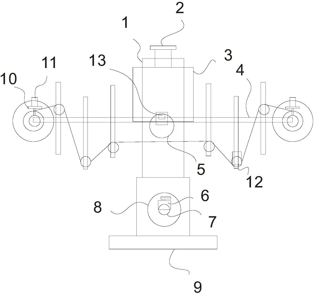
[0012] In order to enable those skilled in the art to better understand the technical solutions of the present invention, the present invention will be further described in detail below in conjunction with the accompanying drawings and preferred embodiments.

[0013] As shown in the figure, the present invention includes a machine base 9, a frame 1 arranged on the machine base, a barrel fixed mold core 8 connected vertically to the front end of the frame through a rotating shaft 7 and a barrel fixed mold The thermal transfer frame 3 connected to the upper end of the core and the frame by a lead screw 2, the thermal transfer frame includes a thermal transfer frame frame body, a thermal transfer film guide frame 4 and a device set at the front end of the thermal transfer frame frame body The heat transfer roller 5 driven by the air cylinder to move downwardly at the lower part of the heat transfer frame body, the heat transfer film feed roller and the waste film take-up roller ar...


PUM


Abstract

The invention relates to heat transfer printing equipment with high printing quality. The heat transfer printing equipment comprises a stand, a frame, a charging barrel fixing mold core, and a heat transfer printing frame connected with the frame through a lead screw, wherein the heat transfer printing frame comprises a heat transfer printing frame body, a heat transfer printing film guide frame and a heat transfer printing roller; a heat transfer printing film inlet roller and a waste film collecting roller are respectively mounted at the two ends of the heat transfer printing film guide frame; and a manual adjusting device and a laser calibrator are arranged on each of the heat transfer printing film inlet roller and the waste film collecting roller. The distance between the heat transfer printing roller and the charging barrel fixing mold core is changed and adjusted through the lead screw, so that the pressure therebetween can be adjusted to an optimal value; a printed pattern is guaranteed to be parallel to a charging barrel through the laser calibrators so as to improve the printing quality; a photoelectric sensor is arranged on the heat transfer printing film guide frame, and the control end of the photoelectric sensor is connected with the cylinder for detecting a heat transfer printing film control point; the cylinder automatically drives the heat transfer printing roller to vertically move to finish the printing, so that the efficiency is improved; and a temperature sensor is arranged in the heat transfer printing roller, and the control end of the temperature sensor is connected with heating equipment of the heat transfer printing roller for controlling the temperature of the heat transfer printing roller so as to guarantee the printing quality.

Description

technical field [0001] The invention relates to a thermal transfer printing device, in particular to a thermal transfer printing device with high printing quality. Background technique [0002] Thermal transfer printing equipment is the equipment that completes the thermal transfer printing process. Thermal transfer printing is an emerging printing process. The printing method of this process is divided into two parts: transfer film printing and transfer printing processing. The transfer film printing adopts screen printing, and the pattern is printed on the surface of the film in advance. The printed pattern is rich in layers, bright in color, ever-changing, small in color difference, and reproducible. Good, it can achieve the effect required by the designer, and it is suitable for mass production; the transfer printing process is processed by a heat transfer machine, that is, heating and pressing, and the exquisite pattern on the transfer film is transferred to the surface...

Claims


Application Information

Patent Timeline
Patent Type & Authority Applications(China)
IPC IPC(8): B41F16/00
Inventor 刘克宝
Owner TIANJIN BINHAI XIANGBAO PLASTIC PROD
Why Eureka
Try Eureka