Ink cartridge for inkjet printer
A technology of inkjet printers and ink cartridges, which is applied in printing and other fields, and can solve problems such as low detection accuracy and complex structure of detection mechanisms
- Summary
- Abstract
- Description
- Claims
- Application Information
AI Technical Summary
Problems solved by technology
Method used
Image
Examples
Embodiment 1
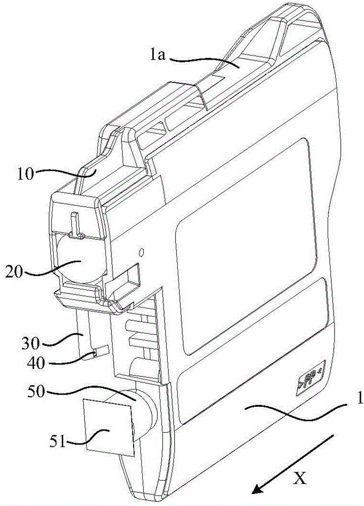
[0031] figure 1 Shown is a perspective view of the ink cartridge of the present invention, and the ink cartridge shown in the figure is in the installed state. The direction indicated by the arrow X in the figure is the installation direction of the ink cartridge. The following expressions related to the orientation are all based on the ink cartridge in this state.
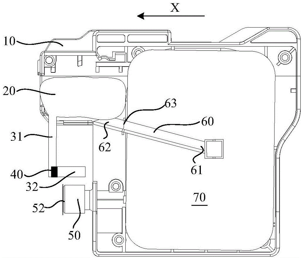
[0032] The ink cartridge includes a box body 1, and the box body 1 is formed by fastening a bottom case and a surface cover. The first detection part 10 protrudes from the upper surface 1 a of the ink cartridge, and the front side of the ink cartridge in the installation direction is formed with a deformable cavity 20 , a transparent tube body 30 and an ink supply part 50 . The deformable cavity 20 is arranged in the space formed between the two housings, and can be in contact with the outside world through the through hole on the front side of the ink cartridge. The hole is in contact with the deformable cavity ...
Embodiment 2
[0040] like Figure 7 Shown is a schematic structural diagram of the ink cartridge according to the second embodiment of the invention. In the figure, the mechanism of the face cover is omitted, which can conveniently and intuitively display the internal structural features of the ink cartridge.
[0041] This embodiment cancels the lever 60, the movable part 40 is located in the transparent tube body, and the sealing between the transparent tube body is good, and the transparent tube body is divided into a first tube body 31 and a second tube body 32, the first tube body 31 communicates with the deformable chamber 20 , and the second tube body 32 communicates with the ink storage chamber 70 . In this embodiment, the ink storage chamber 70 can be in any form that does not communicate with the outside atmosphere, and can be the same as the first embodiment. At least one outer wall of the ink storage chamber 70 is made of a deformable film, and can also be different from the embo...
Embodiment 3
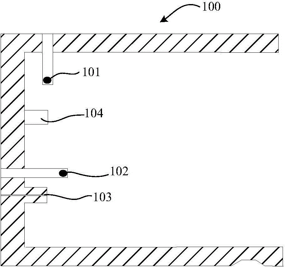
[0048] like Figure 12 and Figure 13 Shown is the third embodiment of the present invention, this embodiment cancels the variable cavity, and sets up the channel at the corresponding position, and the projection 82 is set in this channel, when the ink cartridge is installed, the protrusion in the ink cartridge installation part of the printer 104 is in contact with the protrusion 82, and can push the protrusion 82 to move with the installation of the ink cartridge. When the ink cartridge is taken out from the printer, the protrusion 82 can return to its original position under the elastic restoring force of the spring 83. The part of the lower end of the bump 82 in contact with the channel is provided with a magnetic component, for example, a magnetic block 81 is used in this embodiment. The transparent tube body 30 is fixed on the ink cartridge body and separated from the ink storage chamber. The movable part 40 is arranged in the transparent tube body and can move relative...
PUM
 Abstract
Description
Claims
Application Information
 - R&D
- Intellectual Property
- Life Sciences
- Materials
- Tech Scout
- Unparalleled Data Quality
- Higher Quality Content
- 60% Fewer Hallucinations
Browse by: Latest US Patents, China's latest patents, Technical Efficacy Thesaurus, Application Domain, Technology Topic, Popular Technical Reports.
© 2025 PatSnap. All rights reserved.Legal|Privacy policy|Modern Slavery Act Transparency Statement|Sitemap|About US| Contact US: help@patsnap.com


