
Pressure relief valve assembly for pressure gauges

A technology of a pressure relief valve and a pressure gauge, which is applied in the field of pressure relief valve devices, can solve problems such as difficulty for users to accurately control the amount of deflation, excessive deflation of inflatable items, and excessive deflation rate of the pressure relief valve.

Active Publication Date: 2016-10-19
JIAO HSIUNG IND CORP
View PDF5 Cites 0 Cited by
  • Summary
  • Abstract
  • Description
  • Claims
  • Application Information

AI Technical Summary

Problems solved by technology

However, the deflating speed of the pressure relief valve is usually too high, and it is difficult for the user to accurately control the deflating amount, so the inflatable items are often over-deflated and need to be inflated again

Method used


Image

  • Pressure relief valve assembly for pressure gauges
  • Pressure relief valve assembly for pressure gauges
  • Pressure relief valve assembly for pressure gauges

Examples


Embodiment Construction

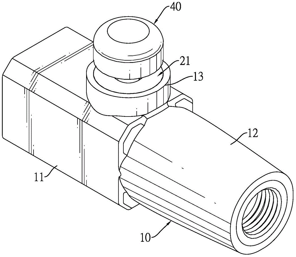
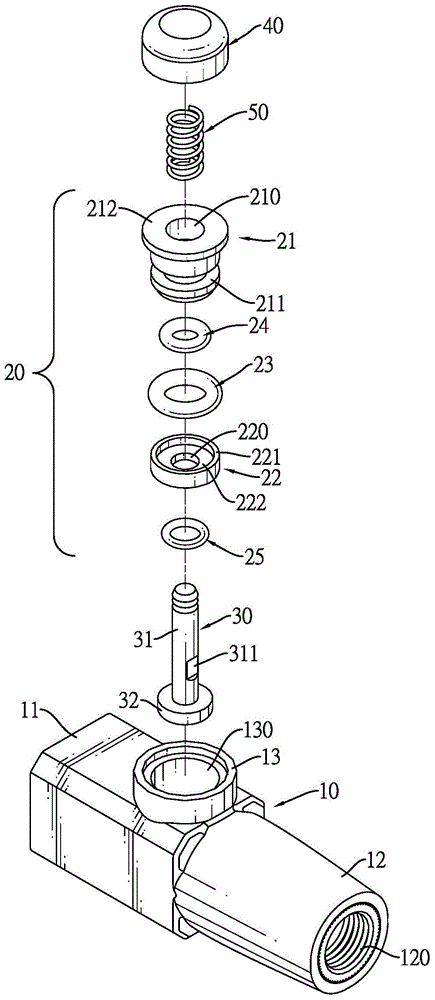
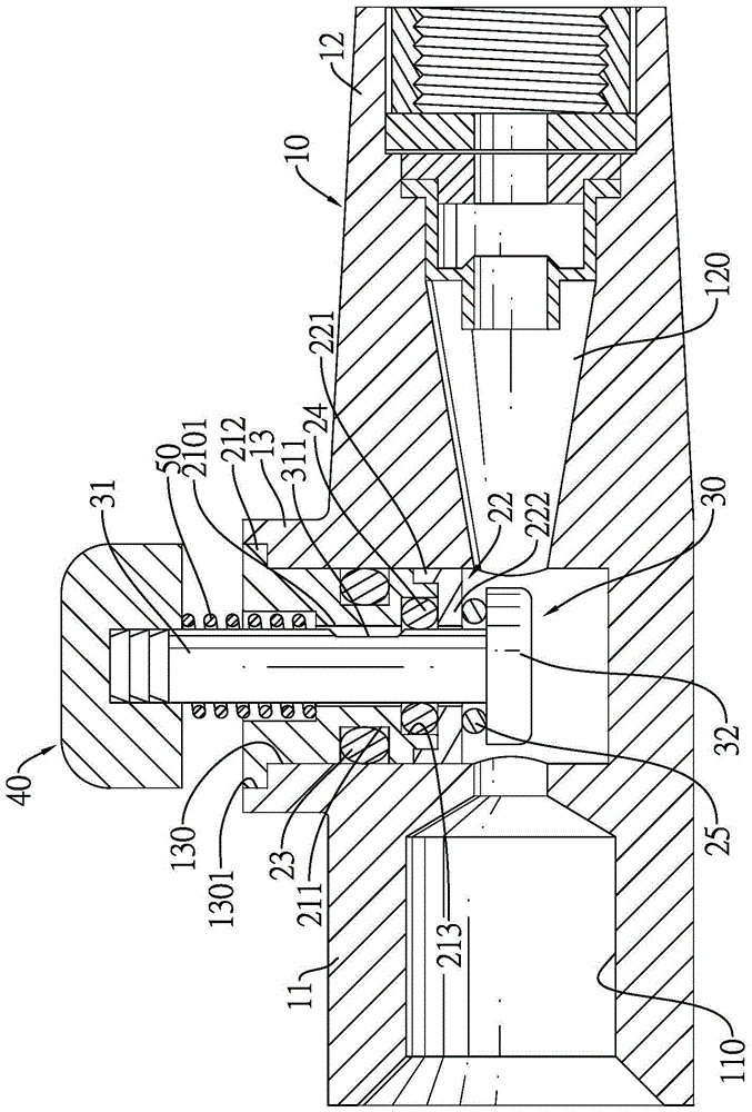
[0039] Please refer to figure 1 , figure 2 and Figure 5 , the pressure relief valve device suitable for pressure gauges of the present invention can be assembled with a pressure gauge body 90 and a probe 80 to form a pressure gauge. The pressure gauge body 90 has a display screen 91 to display the pressure value. In addition, the pressure gauge The body 90 can be an electronic type, a pointer type or a pen type. The probe 80 can be penetrated into an inflation hole of an inflatable item such as a tire or a balloon to detect internal pressure.

[0040] The pressure relief valve device includes: a housing 10 , a pressure relief valve assembly 20 , a valve stem 30 , a button 40 and a spring 50 .

[0041] The housing 10 has a connection part 11, a pressure detection part 12 and a gas release part 13, the connection part 11 can be installed on the pressure gauge body 90, and a connection hole 110 is formed through the connection part 11 for the pressure gauge body 90 to be com...


PUM


Abstract

The invention relates to a pressure release valve device applicable to a pressure gauge. The pressure release valve device comprises a shell, a pressure release valve assembly and a valve rod, wherein the shell is provided with a connection part, a pressure detection part and an air release part; the pressure detection part is provided with an air channel; the pressure release valve assembly is arranged in the air release part and is provided with a valve seat, a first airtight gasket, a second airtight gasket and a fixed cover; the valve seat is provided with a valve hole; the valve rod is arranged in the pressure release valve assembly in an axial sliding manner and is provided with a first rod part, a valve head and a third airtight gasket; an air release notch is formed in one side of the rod part and the valve head is formed at the inner side end of the rod part; when the valve rod is located at a first position, the valve hole of the valve seat is closed; when the valve rod is located at a second position, the valve hold, the air release notch and the air channel are communicated. The air release notch can be used for slowly releasing air of an inflatable object.

Description

technical field [0001] The invention relates to a pressure relief valve device suitable for a pressure gauge. Background technique [0002] Existing pressure gauges are mainly used to measure the internal pressure of inflatable items such as tires or basketballs, so as to confirm that the inflatable items reach a preset internal pressure. In addition to the pressure indicator, the pressure gauge usually also has a pressure relief valve, which can properly relieve the pressure of inflatable items with excessive internal pressure. However, the deflating speed of the pressure relief valve is generally too high, and it is difficult for the user to precisely control the deflating amount, so the inflatable items are often over-deflated and need to be inflated again. Contents of the invention [0003] In view of the shortcomings of traditional pressure gauges that cannot accurately control the amount of air leakage, the inventors improved the problems and defects, and further in...

Claims


Application Information

Patent Timeline
Patent Type & Authority Patents(China)
IPC IPC(8): G01L17/00
Inventor 朱耿锋
Owner JIAO HSIUNG IND CORP
Learn More