
Anti-splashing electric ball valve with long service life

An electric ball valve, anti-splash technology, applied in the direction of valve details, valve devices, engine components, etc., can solve the problems of ball valve service life impact, water flow rate is difficult to control, flow limiting effect is poor, etc., to improve the actual service life, good Anti-creep characteristics, change the effect of component rusting

Pending Publication Date: 2017-12-29
FLUOROSEAL SPECIALTY VALVES SUZHOU
View PDF5 Cites 0 Cited by
  • Summary
  • Abstract
  • Description
  • Claims
  • Application Information

AI Technical Summary

Problems solved by technology

[0002] The electric ball valve is an important actuator in the industrial automation control system. The electric ball valve is a valve that rotates around the axis of the valve stem according to the movement of the valve disc. The change of the valve seat port is proportional to the valve disc stroke. It is mainly used to cut off or connect the medium in the pipeline, and can also be used for the regulation and control of the fluid. It is a pipeline pressure component for industrial automation process control; The form of direct contact between the rotating rod and the valve housing body directly leads to the occurrence of rust and death of the components, and the actual service life of the entire ball valve is affected. Once the water flow is too large and the splashing phenomenon is caused, the flow rate of the water body is difficult to control, and the current limiting effect Also poor, need to solve the above problems

Method used


Image

  • Anti-splashing electric ball valve with long service life
  • Anti-splashing electric ball valve with long service life

Examples


Embodiment Construction

[0013] The following will clearly and completely describe the technical solutions in the embodiments of the present invention with reference to the accompanying drawings in the embodiments of the present invention. Obviously, the described embodiments are only some, not all, embodiments of the present invention. Based on the embodiments of the present invention, all other embodiments obtained by persons of ordinary skill in the art without making creative efforts belong to the protection scope of the present invention.

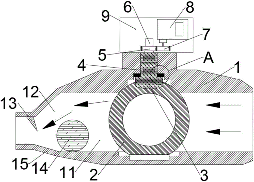
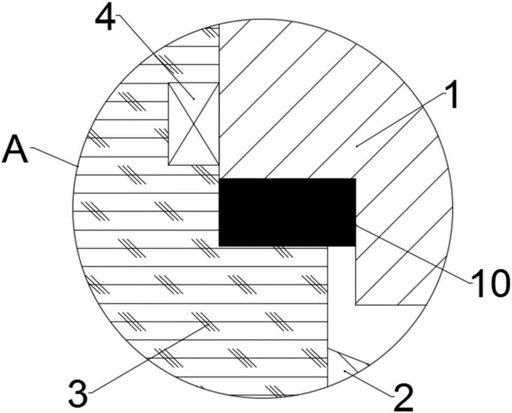
[0014] see Figure 1-2 , in an embodiment of the present invention, a high-life anti-splash electric ball valve includes a valve housing body 1, a valve ball 2 is arranged in the valve inner cavity of the valve housing body 1, and the outer side of the circular top end of the valve ball 2 is A valve core rotating rod 3 is arranged on the wall, and the rod body of the valve core rotating rod 3 includes a lower end head fixed integrally with the valve ball 2 and...


PUM


Abstract

The invention discloses an anti-splashing electric ball valve with long service life. The anti-splashing electric ball valve with long service life comprises a valve casing body, wherein a valve ball is arranged in a valve body inner cavity of the valve casing body; a rod body of a valve core rotating rod comprises a lower end head and an upper end head; the lower end head and the valve ball are integrated and fixedly arranged; the top of the upper end head passes through the top side wall of the valve casing body; a buffer ring gasket is arranged at a position between the lower end head of the valve core rotating rod and the valve casing body; the cross section of the buffer ring gasket is ring-shaped; a hollow ball is arranged in the inner cavity of a water discharging end; an inclined side plate surface is formed below an anti-skip shift bulge and corresponds to the bottom end surface of the valve casing body; and a ball body limiting point of the hollow ball is formed between the inclined side plate surface and the anti-skip shift bulge. The anti-splashing electric ball valve with long service life has the beneficial effects that the good sealing property and the shock absorption buffering effect can be realized in the rotating process of the whole valve core rotating rod; the manual adjustment is not needed; and a splashing phenomenon caused by excessive water flow is avoided very well.

Description

technical field [0001] The invention relates to the technical field related to valves, in particular to a high-life splash-proof electric ball valve. Background technique [0002] The electric ball valve is an important actuator in the industrial automation control system. The electric ball valve is a valve that rotates around the axis of the valve stem according to the movement of the valve disc. The change of the valve seat port is proportional to the valve disc stroke. It is mainly used to cut off or connect the medium in the pipeline, and can also be used for the regulation and control of the fluid. It is a pipeline pressure component for industrial automation process control; The form of direct contact between the rotating rod and the valve housing body directly leads to the occurrence of rust and death of the components, and the actual service life of the entire ball valve is affected. Once the water flow is too large and the splashing phenomenon is caused, the flow ra...

Claims


Application Information

Patent Timeline
Patent Type & Authority Applications(China)
IPC IPC(8): F16K5/06F16K5/10F16K31/04F16K31/53
CPCF16K5/0647F16K5/0663F16K5/10F16K31/043F16K31/535
Inventor 田洪卫欧丹
Owner FLUOROSEAL SPECIALTY VALVES SUZHOU
Learn More