Micro-mechanical film structure of MEMS device and MEMS device

A thin-film structure and micro-mechanical technology, applied in the field of components, can solve the problems of MEMS device performance drift, MEMS device failure, high risk, etc., and achieve the effect of avoiding performance drift and improving creep resistance characteristics

Pending Publication Date: 2022-05-13
TSINGHUA UNIV
View PDF0 Cites 0 Cited by
  • Summary
  • Abstract
  • Description
  • Claims
  • Application Information

AI Technical Summary

Problems solved by technology

Micromechanical thin film structures are generally composed of metal materials or non-metal materials. For these materials (especially metal materials), under the condition of mechanical stress during operation, due to their creep characteristics, MEMS devices will gradually produce irreversible deformation. , so that the performance of MEMS devices will drift, and in severe cases, it will even cause MEMS devices to fail
[0003] In order to alleviate the creep deterioration of the structure, the industry generally uses high-strength creep-resistant new materials to improve performance; however, this method requires the development and evaluation of new materials, which has a long cycle and high risk, and the development results are somewhat unpredictable

Method used


Image

  • Micro-mechanical film structure of MEMS device and MEMS device
  • Micro-mechanical film structure of MEMS device and MEMS device
  • Micro-mechanical film structure of MEMS device and MEMS device

Examples


Embodiment Construction

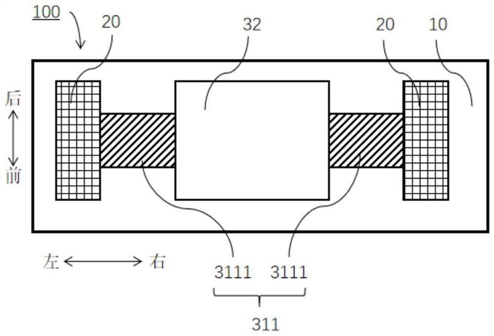
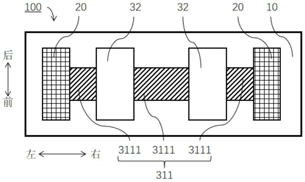
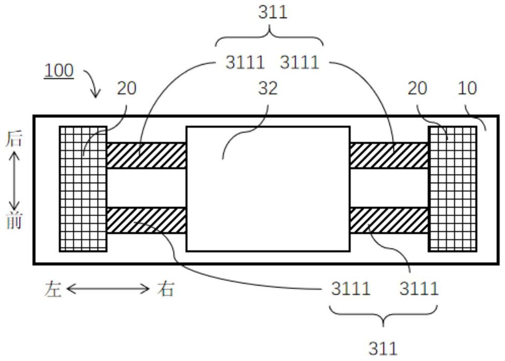
[0034] Embodiments of the present invention are described in detail below, examples of which are shown in the drawings, wherein the same or similar reference numerals designate the same or similar elements or elements having the same or similar functions throughout. The embodiments described below by referring to the figures are exemplary only for explaining the present invention and should not be construed as limiting the present invention.

[0035] In describing the present invention, it should be understood that the terms "center", "longitudinal", "transverse", "length", "width", "thickness", "upper", "lower", "front", " Back", "Left", "Right", "Vertical", "Horizontal", "Top", "Bottom", "Inner", "Outer", "Clockwise", "Counterclockwise", "Axial" , "radial", "circumferential" and other indicated orientations or positional relationships are based on the orientations or positional relationships shown in the drawings, which are only for the convenience of describing the present ...


PUM


Abstract

The invention discloses a micro-mechanical thin film structure of an MEMS device and the MEMS device. The micro-mechanical thin film structure comprises a substrate; the anchor point seat is arranged on the substrate; the elastic thin film assembly comprises a thin film piece and a stress absorbing piece, the stress absorbing piece is arranged on the thin film piece to absorb stress causing creep deformation of the thin film piece, and one of the thin film piece and the stress absorbing piece is arranged on the anchor point seat. According to the invention, the stress absorbing part is arranged to absorb the stress causing creep deformation of the thin film part, so that the concentrated stress on the elastic thin film assembly is released or homogenized, the creep resistance is improved, and the performance of the MEMS device is prevented from drifting.

Description

technical field [0001] The invention relates to the field of components of MEMS devices, in particular to a micromechanical thin film structure of the MEMS device and the MEMS device. Background technique [0002] Micromechanical thin film structures are typical components in MEMS (microelectromechanical systems) devices, and are often used for structural actuation, signal sensing, etc. Micromechanical thin film structures are generally composed of metal materials or non-metal materials. For these materials (especially metal materials), under the condition of mechanical stress during operation, due to their creep characteristics, MEMS devices will gradually produce irreversible deformation. , so that the performance of the MEMS device will drift, and even cause the failure of the MEMS device in severe cases. [0003] In order to alleviate the creep deterioration of the structure, the industry generally uses high-strength creep-resistant new materials to improve performance;...

Claims


Application Information

Patent Timeline
Patent Type & Authority Applications(China)
IPC IPC(8): B81B7/02B81B7/00
CPCB81B7/02B81B7/0048B81B7/0058B81B2203/0127
Inventor 刘泽文张玉龙
Owner TSINGHUA UNIV
Why Eureka
Try Eureka