Waste gas treatment device with deodorization function

A waste gas treatment device and functional technology, applied in the field of waste gas treatment devices with deodorization function

Pending Publication Date: 2022-07-22
广州科威环保工程有限公司
View PDF8 Cites 0 Cited by
  • Summary
  • Abstract
  • Description
  • Claims
  • Application Information

AI Technical Summary

Problems solved by technology

[0004] Aiming at the deficiencies of the prior art, the present invention provides a waste gas treatment device with a deodorizing function, which solves the problem that the existing equipment proposed in the above-mentioned background technology cannot deodorize the odor in the gas

Method used


Image

  • Waste gas treatment device with deodorization function
  • Waste gas treatment device with deodorization function
  • Waste gas treatment device with deodorization function

Examples


Embodiment 1

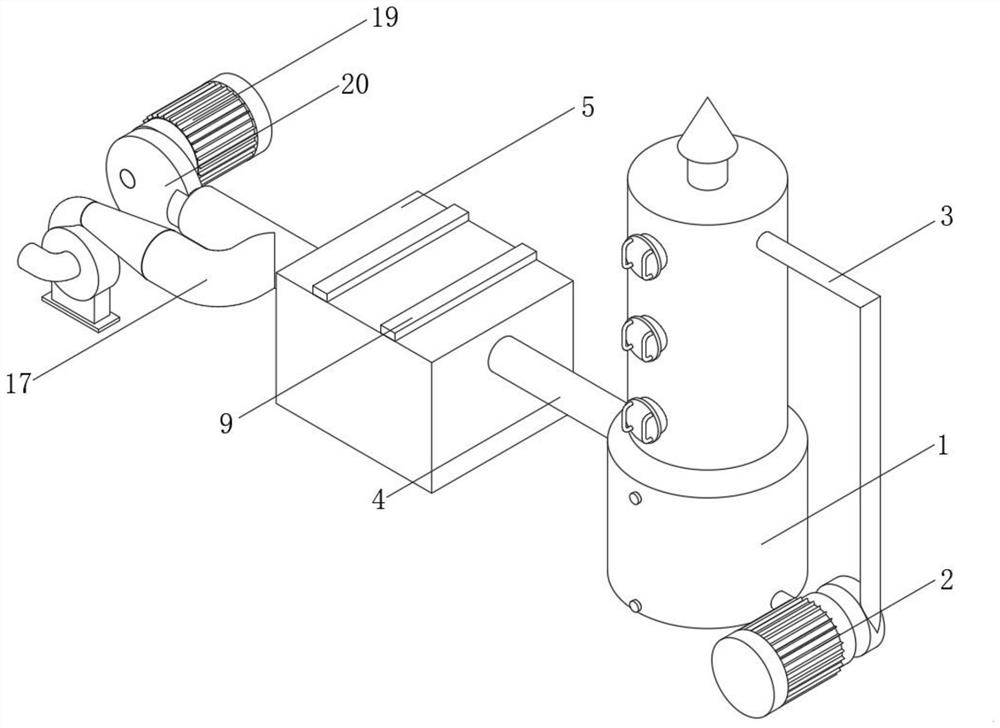
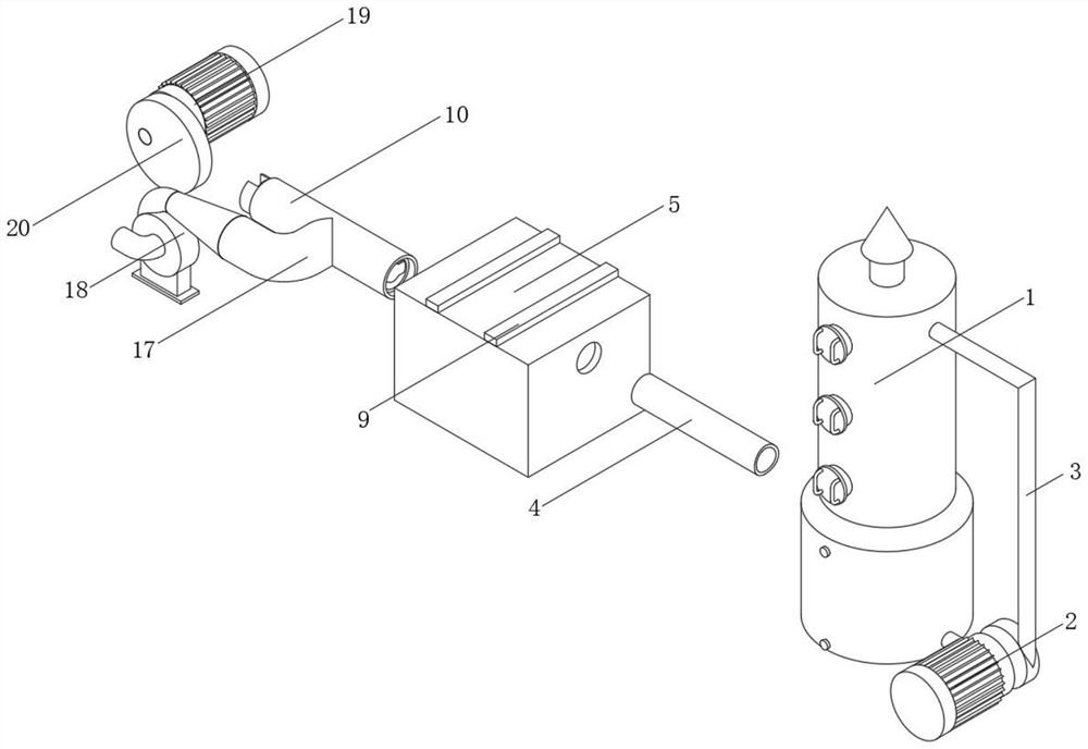
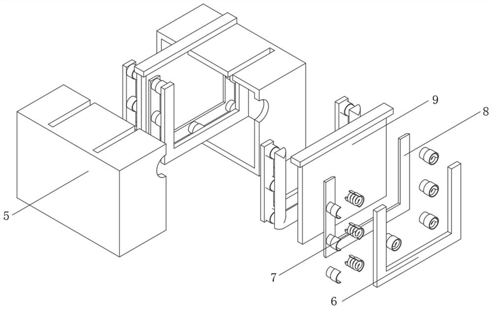
[0045] see Figure 1 to Figure 3 , the present invention provides a technical solution: the inner cavity of the deodorant box 5 is fixedly installed with a fixed frame 6, one side of the fixed frame 6 is fixedly connected with a support spring 7, and the side of the support spring 7 away from the fixed frame 6 is fixedly connected with a clip The holding sleeve 8 is provided with a bamboo charcoal plate 9 on one side of the holding sleeve 8 away from the fixing frame 6 . The fixed frame 6, the supporting spring 7 and the clamping sleeve 8 are all arranged into two groups, the bamboo charcoal plate 9 is located between the two clamping sleeves 8, and the edges and corners on the inner side of the clamping sleeve 8 are opened as arc surfaces, and the bamboo charcoal plate 9 is used for a period of time. , by pulling out the bamboo charcoal board 9, replace the new bamboo charcoal board 9 subsequently, make the bamboo charcoal board 9 insert from the upper direction of the deodor...

Embodiment 2

[0050] see Figure 5 to Figure 8 , On the basis of Embodiment 1, the spray tower 1 is provided with a flow regulating device 21 , and the flow regulating device 21 is fixed to the spray tower 1 .

[0051] The flow regulating device 21 includes:

[0052] Motor 2101, motor protective shell 2102, connecting shaft 2103, blocking plate 2104, communication pipe 2105, first gear 2106, second gear 2107, regulating plate 2108, first through hole 2109, second through hole 2110, third through hole 2111, the third gear 2112;

[0053] The motor 2101 is fixed on the inner upper surface of the spray tower 1 , the motor protection shell 2102 is provided outside the motor 2101 , and the motor protection shell 2102 is fixed to the inner upper surface of the spray tower 1 ;

[0054] The output end of the motor 2101 is fixed with one end of the connecting shaft 2103, and the other end of the connecting shaft 2103 is fixed with the first gear 2106;

[0055] The blocking plate 2104 is arranged b...

Embodiment 3

[0067] On the basis of Embodiment 1, a state parameter detection device of the blocking spring 14 is also included, and the state parameter detection device of the blocking spring 14 includes:

[0068] a displacement sensor, arranged on the restrictor plate 13, for detecting the displacement of the connection end between the restrictor plate 13 and the blocking spring 14;

[0069] a counter, which is set on the restrictor plate 13 and used to record the number of times the blocking spring 14 is compressed;

[0070] an alarm, the alarm is located on the deodorant box 5;

[0071] A controller, the controller is electrically connected with the displacement sensor, the counter and the alarm, respectively, the controller controls the operation of the alarm based on the displacement sensor and the counter, including:

[0072] Step 1: The controller obtains the state parameters of the blocking spring 14 based on the displacement sensor, the counter and the formula (1):

[0073] ...


PUM


Abstract

The invention discloses a waste gas treatment device with a deodorization function, and relates to the technical field of waste gas treatment, in particular to the waste gas treatment device with the deodorization function, the waste gas treatment device comprises a deodorization box, a fixing frame is fixedly mounted in an inner cavity of the deodorization box, and a supporting spring is fixedly connected to the inner side of the fixing frame; clamping sleeves are fixedly connected to the inner sides of the supporting springs, and bamboo charcoal plates are arranged on the inner sides of the two clamping sleeves. According to the waste gas treatment device with the deodorization function, a deodorization box is connected to the left end of a second gas supply pipe, four fixing frames are fixedly arranged in the deodorization box in a sleeving manner, a clamping sleeve is connected between the two fixing frames through a supporting spring, and meanwhile, a bamboo charcoal plate is inserted between the two clamping sleeves during use, so that the bamboo charcoal plate can conveniently pass through the clamping sleeves; the two bamboo charcoal plates adsorb peculiar smell in gas entering the spray tower, and the gas is deodorized, so that the discharged gas is prevented from influencing the living environment of surrounding residents.

Description

technical field [0001] The invention relates to the technical field of waste gas treatment, in particular to a waste gas treatment device with deodorizing function. Background technique [0002] Waste gas treatment equipment mainly refers to an environmental protection equipment that protects the environment and purifies the air by recovering or removing and reducing harmful components of exhaust gas by using different process technologies, so that our environment is not polluted. The non-volatile solvent absorbs VOCs, and then separates them by using the difference in physical properties of VOCs and absorbents. The gas containing VOCs enters the tower from the bottom of the absorption tower, and contacts the absorbent from the top of the tower in countercurrent during the ascending process. After purification The gas is discharged from the top of the tower, and the absorbent that absorbs VOCs passes through the heat exchanger and enters the top of the stripping tower, where...

Claims


Application Information

Patent Timeline
Patent Type & Authority Applications(China)
IPC IPC(8): B01D53/04B01D53/18
CPCB01D53/04B01D53/0407B01D53/18B01D53/185B01D53/1412
Inventor 刘勤
Owner 广州科威环保工程有限公司
Why Eureka
Try Eureka