Motor actuator

A technology of actuators and motors, applied in the direction of electric components, casings/covers/supports, control of mechanical energy, etc., can solve problems such as abnormal sound, failure to obtain predetermined driving force, etc., and achieve the effect of preventing flying

Active Publication Date: 2015-03-18
TOKYO PARTS IND CO LTD
View PDF4 Cites 6 Cited by
  • Summary
  • Abstract
  • Description
  • Claims
  • Application Information

AI Technical Summary

Problems solved by technology

Therefore, if the gap between the rotating shaft and the notch is small, the rotating shaft will come into contact with the oppo

Method used


Image

  • Motor actuator
  • Motor actuator

Examples


Embodiment approach

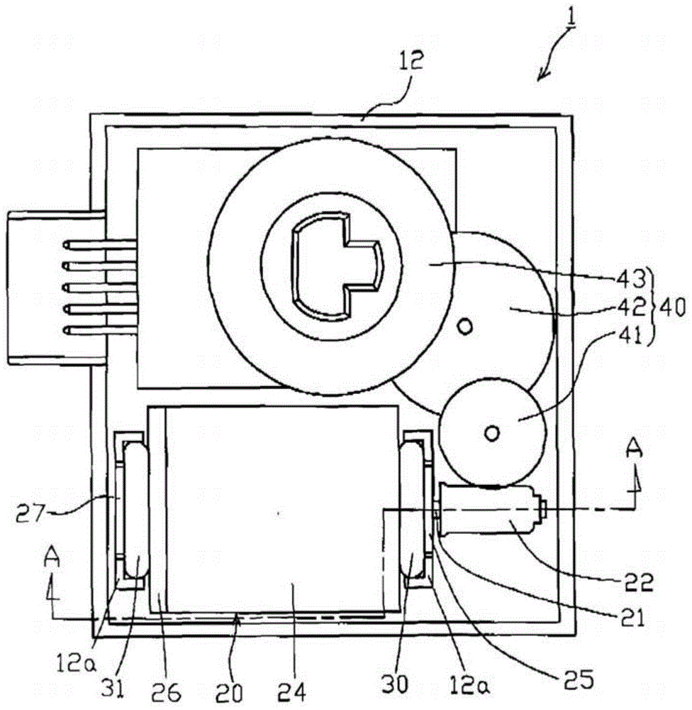
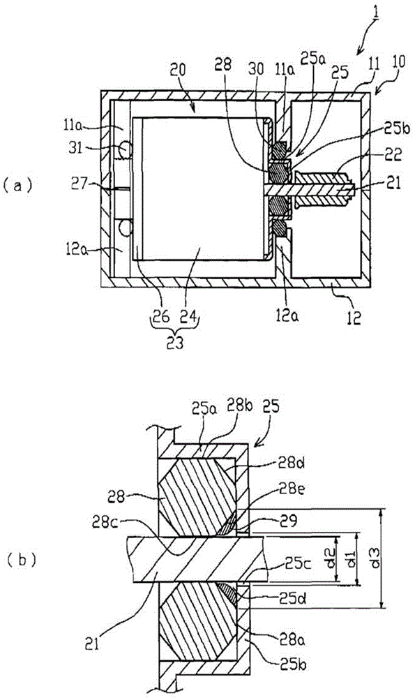
[0056] Such as figure 1 and figure 2 As shown, the motor actuator 1 of this example is used as a drive source for an air flow adjustment valve of an air conditioner used in vehicles such as automobiles, and accommodates a motor 20 in a casing 10 having a space inside and rotates the motor 20. The deceleration mechanism 40 for deceleration.

[0057] The case 10 has an upper case 11 and a lower case 12 made of hard resin, and the opening ends of the upper case 11 and the lower case 12 are fitted into each other to form a box shape having a predetermined internal space. In addition, since the fitting structure of the upper case 11 and the lower case 12 is not an essential part of the present invention, it is omitted from the drawings.

[0058] The motor 20 of this example is constituted by a DC motor with a brush, and has a motor case 23 and a rotating shaft 21 having a space inside. One end of the rotating shaft 21 protrudes to the outside of the motor case 23 , and a worm 2...


PUM


Abstract

The invention provides a motor actuator which can effectively prevent lubricating grease from being sprayed out. The motor (20) comprises a motor housing (23), which comprises a bearing accommodating part (25), wherein an oil-containing bearing is fixedly arranged in the bearing accommodating part (25); and a rotation shaft (21) which stretches out from the bearing accommodation part (25) to the motor housing (23). The motor housing (23) is elastically supported on a shell (10) by O-shaped rings (30,31). The bearing accommodating part (25) comprises a cylindrical part (25a), an accommodated oil-containing bearing, and a flange part which is opposite to the external end surface (28a) of the oil-containing bearing in the axial direction, and an opening part (25c) for inserting a rotation shaft is formed. The oil-containing bearing is provided with a second chamfering part (28e), which is coated by lubricating grease (29), in the inner circumferential side of the external end surface in the axial direction. The inner diameter (d1) of the opening part is arranged to be larger than the external diameter (d2) of the rotation shaft, and smaller than the external diameter (d3) of the second chamfering part.

Description

technical field [0001] The present invention relates to a configuration for preventing grease leakage in a motor actuator. Background technique [0002] Conventionally, a motor actuator driven by a motor is known as a drive source of an air damper valve of an air conditioner used in a vehicle such as an automobile. [0003] Such a motor actuator generally accommodates a motor and a reduction mechanism of the motor in a housing case in which a cover is assembled to a case body. In addition, the motor includes a motor housing having a pair of boss portions protruding in the axial direction, and a rotating shaft on which is mounted a worm protruding from one of the boss portions to the outside of the motor housing and meshing with the worm wheel. In addition, a pair of case-side supporting pieces and a cover-side supporting piece for supporting the motor via elastic members (O-rings) attached to the outer peripheries of the respective bushing portions are provided on the case ...

Claims


Application Information

Patent Timeline
IPC IPC(8): H02K5/16H02K7/10
CPCH02K5/16H02K7/10
Inventor 渡边裕司
Owner TOKYO PARTS IND CO LTD
Why Eureka
Try Eureka