Method for automatically controlling power of optical transceiver

A technology of optical transceivers and optical power, applied in electromagnetic wave transmission systems, electromagnetic receivers, electrical components, etc., can solve the problems of low stability of luminous power, achieve high slew rate, improve flexibility, and sufficient steady-state current

Inactive Publication Date: 2015-03-18
熊凌聪
View PDF0 Cites 2 Cited by
  • Summary
  • Abstract
  • Description
  • Claims
  • Application Information

AI Technical Summary

Problems solved by technology

[0003] The invention provides a method for automatically controlling the power of an optical transceiver to solve the

Method used


Image

  • Method for automatically controlling power of optical transceiver

Examples


Embodiment 1

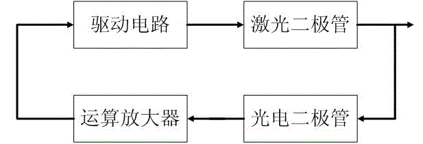
[0017] Such as figure 1 As shown, a method for clamping and clamping logs of the present invention is realized through the following steps: (A) including a drive circuit, a photodiode and a laser diode, the adjustment end of the drive circuit is connected to the laser diode, and the drive circuit The feedback terminal of the laser diode is connected with the photodiode, and the laser diode is connected with the photodiode, and an operational amplifier connected with the photodiode is also included, and the operational amplifier is connected with the feedback terminal of the driving circuit. First, the luminous power of the laser diode is set through the operational amplifier to determine the current flowing through the laser diode. At the same time, the laser diode irradiates a certain proportion of light onto the photodiode, and the photodiode will generate a corresponding current, and the current returns to the operational amplifier. , the luminous power of the laser diode i...


PUM


Abstract

The invention discloses a method for automatically controlling the power of an optical transceiver. An adopted operational amplifier has the characteristics of broad bandwidth, high slew rate and abundant steady-state current, a driver separately designed in a photodiode is replaced, and the automatic control on optical power is realized.

Description

technical field [0001] The invention relates to computer network transmission technology, in particular to a method for automatic power control of an optical transceiver. Background technique [0002] The basic function of the optical fiber communication optical transmitter is to convert the electrical signal carrying information into an optical signal, and send the optical signal into the optical fiber. The light source is a key component in the optical fiber communication system. The development of optical fiber communication technology and the development of light source technology are Inseparable. Semiconductor lasers are ideal light sources for high-speed modulation. Semiconductor lasers are very sensitive to temperature changes. Temperature changes and device aging bring instability to the laser, resulting in great changes in output power. In order to ensure normal and smooth communication, the luminous power of the optical transmitter should be kept at a constant val...

Claims


Application Information

Patent Timeline
IPC IPC(8): H04B10/564H04B10/69
Inventor 熊凌聪
Owner 熊凌聪
Why Eureka
Try Eureka