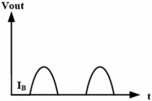
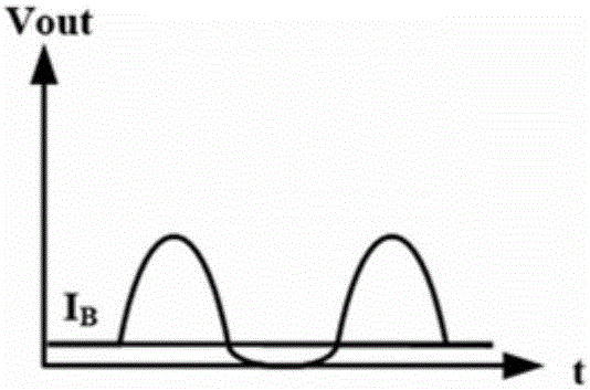
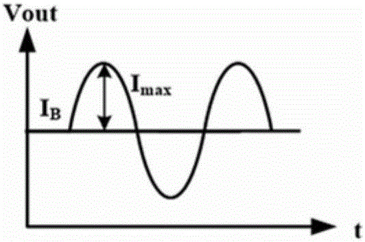
Slew rate enhancement type operational amplifier

An operational amplifier and slew rate enhancement technology, which is applied in the direction of amplifiers, differential amplifiers, DC-coupled DC amplifiers, etc., can solve the problems of crossover distortion operational amplifier structure, increase the bias current of the output stage, and cannot meet low power consumption, etc. Achieve the effects of avoiding crossover distortion, increasing slew rate, and increasing static power consumption

Active Publication Date: 2017-01-04
SHANGHAI ADVANCED RES INST CHINESE ACADEMY OF SCI
View PDF6 Cites 3 Cited by
  • Summary
  • Abstract
  • Description
  • Claims
  • Application Information

AI Technical Summary

Problems solved by technology

[0006] In view of the above-mentioned shortcoming of prior art, the object of the present invention is to provide a kind of slew rate enhanced operational amplifier, is used to solve the problem that the two-stage transconductance operational amplifier in the prior art improves the slew rat

Method used


Image

  • Slew rate enhancement type operational amplifier
  • Slew rate enhancement type operational amplifier
  • Slew rate enhancement type operational amplifier

Examples


Embodiment Construction

[0051] Embodiments of the present invention are described below through specific examples, and those skilled in the art can easily understand other advantages and effects of the present invention from the content disclosed in this specification. The present invention can also be implemented or applied through other different specific implementation modes, and various modifications or changes can be made to the details in this specification based on different viewpoints and applications without departing from the spirit of the present invention.

[0052] see image 3 and Figure 4 , the first embodiment of the present invention relates to a slew rate enhanced operational amplifier. It should be noted that the diagrams provided in this embodiment are only schematically illustrating the basic idea of ​​the present invention, and only the components related to the present invention are shown in the diagrams rather than the number, shape and shape of the components in actual imple...


PUM


Abstract

The invention provides a slew rate enhancement type operational amplifier, which at least comprises a biasing circuit, a first-stage circuit, a second-stage circuit and a drive current regulating circuit, wherein the first-stage circuit is connected to the biasing circuit; the second-stage circuit is respectively connected to the biasing circuit and the first-stage circuit; and the drive current regulating circuit is respectively connected to the biasing circuit, the first-stage circuit and the second-stage circuit and is used for regulating the drive current of the slew rate enhancement type operational amplifier when the slew rate enhancement type operational amplifier drives a load in order to make the drive current of the slew rate enhancement type operational amplifier greater than the bias current to enhance the slew rate of the slew rate enhancement type operational amplifier. In comparison with the class-A operational amplifier in the existing technology, the magnitude of the drive current of the slew rate enhancement type operational amplifier is not decided by the bias current of an output stage, and the drive current can be much larger than the bias current, so that quick charge and discharge under the large capacitance load can be realized without improving the bias current of the output stage, and thus the slew rate is greatly improved.

Description

technical field [0001] The invention relates to the technical field of operational amplifiers, in particular to a slew rate enhanced operational amplifier. Background technique [0002] Operational amplifiers are widely used in the field of analog integrated circuits and are one of the most important modules in digital-analog hybrid circuits. They play a key role in consumer electronics, control and signal conversion systems, and communication systems. For different application fields, the system has different requirements for operational amplifiers. In audio and video signal acquisition, processing and communication system applications, such as LCD display panel driver chips, speaker device drivers, etc., it is usually required that the operational amplifier can drive large loads (such as capacitive loads, resistive loads, etc.) and provide sufficient voltage swing rate and remains stable over large variations in load capacitance. [0003] The slew rate (Slew Rate, SR, or...

Claims


Application Information

Patent Timeline
IPC IPC(8): H03F3/45
CPCH03F3/45188
Inventor 汪辉黄尊恺田犁章琦汪宁叶汇贤黄景林
Owner SHANGHAI ADVANCED RES INST CHINESE ACADEMY OF SCI
Why Eureka
Try Eureka