High-precision current-limiting load switch circuit

A load switch and current limiting technology, which is applied in the field of power electronics, can solve the problems of affecting the response speed of the current limiting load switch circuit, failing to provide a sufficiently high gate drive voltage, reducing the slew rate of the operational amplifier, and achieving small resistance and low Offset voltage, the effect of increasing the slew rate

Active Publication Date: 2020-07-31
XIDIAN UNIV
View PDF9 Cites 4 Cited by
  • Summary
  • Abstract
  • Description
  • Claims
  • Application Information

AI Technical Summary

Problems solved by technology

The traditional amplifier structure has the following disadvantages: (1) The two-stage operational amplifier structure can provide high gain, but it needs to use the Miller capacitor compensation method to improve stability, thereby reducing the slew rate of the operational amplifier and affecting the response of the current-limiting load switching circuit speed; (2) Traditional operational amplifiers will have a certain offset voltage due to design and process problems, which will affect the accuracy of current limiting when used in a current-limiting load switch circuit; (3) cannot provide a high enough voltage when the load is normal Gate drive voltage

Method used


Image

  • High-precision current-limiting load switch circuit
  • High-precision current-limiting load switch circuit
  • High-precision current-limiting load switch circuit

Examples


Embodiment Construction

[0026] The following is a further description of the embodiments of the present invention with reference to the accompanying drawings.

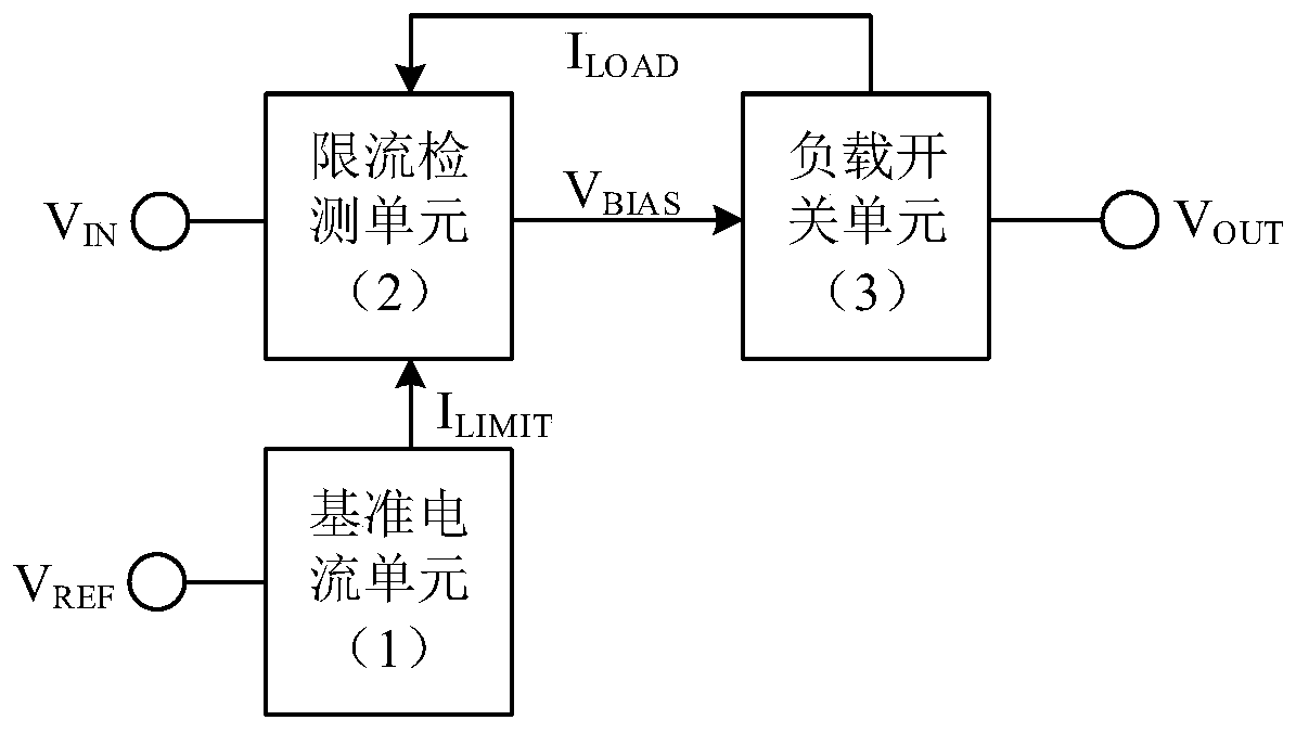
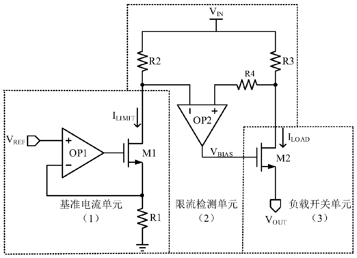
[0027] refer to figure 1 , the load switch circuit provided by the present invention includes: a reference current unit 1, a current limit detection unit 2 and a load switch unit 3; wherein the reference current unit 1 is provided with an input terminal connected to a reference voltage V REF , with an output output reference current I LIMIT ; The current-limiting detection unit 2 is provided with three input terminals, which are respectively connected to the middle reference current I LIMIT , load current I LOAD and input supply V IN , featuring an output output bias voltage V BIAS ; The load switch unit 3 is provided with an input terminal, which is connected to the bias voltage V BIAS , with two output terminals, respectively connected to the load current I LOAD and load voltage V OUT .

[0028] The reference current unit 1 is used ...


PUM


Abstract

The invention discloses a high-precision current-limiting load switch circuit, a current-limiting load switch is connected between a power supply and a load, and the current-limiting load switch circuit mainly solves the problems of low precision and the low response speed of the existing current-limiting load switch circuit. The current-limiting load switch circuit comprises a reference current unit (1), a current-limiting detection unit (2) and a load switch unit (3), the reference current unit is used for generating a stable reference current signal and setting a limiting current; the current-limiting detection unit is used for detecting load current and outputting bias voltage to drive an NMOS load switch. When the load switch unit works in a deep linear region, the conduction impedance is small, and the power supply utilization efficiency is higher. Besides, the operational amplifier for the current-limiting detection unit provided by the invention has the lower offset voltage andthe higher slew rate, so that the current-limiting load switch circuit has the characteristics of high precision and the high response speed, and can be used in an intelligent and integrated power supply management system.

Description

technical field [0001] The invention relates to the technical field of power electronics, in particular to a load switch integrated circuit with current limiting protection, which can be used in power management systems. Background technique [0002] The current-limiting load switch circuit is an important part of the protection circuit in the power management system. When the circuit is overloaded and short-circuited, the load current reaches several amperes, and an accurate current-limiting circuit is required to provide protection for the power tube and the input power supply. Management systems have significant value. [0003] Since an operational amplifier circuit with high open-loop gain is required in a current-limited load switch to form the sense feedback loop, the design of the amplifier will affect the performance of the current-limited load switch. The traditional amplifier structure has the following disadvantages: (1) The two-stage operational amplifier struc...

Claims


Application Information

Patent Timeline
Patent Type & Authority Applications(China)
IPC IPC(8): H03K17/06H03K17/08
CPCH03K17/06H03K17/08
Inventor 来新泉蔚道嘉刘晨吴海若刘明明
Owner XIDIAN UNIV
Why Eureka
Try Eureka