
Current-limiting circuit and illumination device

A current-limiting circuit and lighting equipment technology, which is applied to lighting devices, lamp circuit layout, electric light source, etc., can solve the problems of high cost, complex structure, large volume and unsuitable integration of current-limiting circuits, and achieve safe and reliable current, satisfying Effect of volume and cost requirements

Inactive Publication Date: 2015-03-18
OCEANKING DONGGUAN LIGHTING TECH +2
View PDF7 Cites 1 Cited by
  • Summary
  • Abstract
  • Description
  • Claims
  • Application Information

AI Technical Summary

Problems solved by technology

However, in some small circuit devices, this type of current limiting circuit has high cost, complex structure, and large volume, which is not suitable for integration

Method used


Image

  • Current-limiting circuit and illumination device
  • Current-limiting circuit and illumination device

Examples


Embodiment Construction

[0022] The following will clearly and completely describe the technical solutions in the embodiments of the present invention with reference to the accompanying drawings in the embodiments of the present invention. Obviously, the described embodiments are only some, not all, embodiments of the present invention. Based on the embodiments of the present invention, all other embodiments obtained by persons of ordinary skill in the art without creative efforts fall within the protection scope of the present invention.

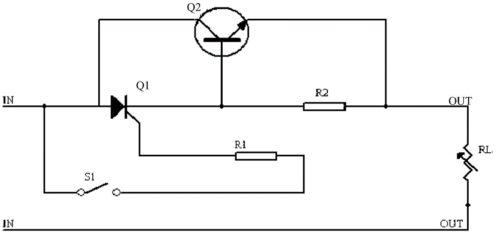
[0023] See figure 1 , is a current limiting circuit diagram of an embodiment of the present invention; the current limiting circuit includes a one-way thyristor Q1, a triode Q2, a switch S1, a resistor R1, a resistor R2 and a load RL, wherein the collector of the triode Q2 is connected to the single connected to the anode of the thyristor Q1, the base of the triode Q2 is connected to the cathode of the one-way thyristor Q1, and a resistor R2 is connected between th...


PUM


Abstract

Embodiments of the invention disclose a current-limiting circuit and an illumination device. The current-limiting circuit comprises a one-way thyristor Q1, a triode Q2, a switch S1, a resistor R1, a resistor R2, and a load RL. The collector electrode of the triode Q2 is connected with the anode of the one-way thyristor Q1. The base electrode of the triode Q2 is connected with the cathode of the one-way thyristor Q1. The resistor R2 is connected between the base electrode and the emitter electrode of the triode Q2. One end of the resistor R1 is connected with one end of the switch S1. The anode of the one-way thyristor Q1 is connected with the other end of the switch S1. The control electrode of the one-way thyristor Q1 is connected with the other end of the resistor R1. The anode of the one-way thyristor Q1 is connected with an input end. The emitter electrode of the triode Q2 is connected with the load RL. The current-limiting circuit and the illumination device are advantaged by simple structure and small volume, and provides safe and reliable current for the load.

Description

technical field [0001] The invention relates to the technical field of circuit design, in particular to a current limiting circuit and lighting equipment. Background technique [0002] A current limiting circuit refers to a circuit that has been properly designed and protected so that a certain amount of current can be input to protect the entire circuit under normal operating conditions or when a circuit fault occurs. The circuit fault can be caused by man-made short circuit, etc., or it can be caused by the sudden increase of current caused by the failure of some components. [0003] In the prior art, the current-limiting circuit generally consists of a rectifier bridge, a current-limiting resistor, a filter capacitor, etc., wherein the current-limiting resistor is connected in series between the rectifier bridge and the filter capacitor. However, in some small circuit devices, this type of current limiting circuit has high cost, complex structure, and large volume, which...

Claims


Application Information

Patent Timeline
Patent Type & Authority Applications(China)
IPC IPC(8): H05B37/02
Inventor 周明杰刘金财
Owner OCEANKING DONGGUAN LIGHTING TECH
Learn More