Auxiliary beam of bogie

An auxiliary beam and bogie technology, applied in the field of rail vehicles, can solve the problems of complex structure, heavy metal beam structure, inconvenient maintenance and replacement, etc.

Pending Publication Date: 2022-02-11
CRRC QINGDAO SIFANG CO LTD
View PDF9 Cites 1 Cited by
  • Summary
  • Abstract
  • Description
  • Claims
  • Application Information

AI Technical Summary

Problems solved by technology

There is an empty spring in the middle of the side beam of the bogie, and the inner cavity of the side beam forms an additional air chamber for the air spring. When the volume is insufficient, an external bellows is also used as an additional air chamber, and the structure is more complicated.
[00

Method used


Image

  • Auxiliary beam of bogie
  • Auxiliary beam of bogie
  • Auxiliary beam of bogie

Examples


Embodiment 1

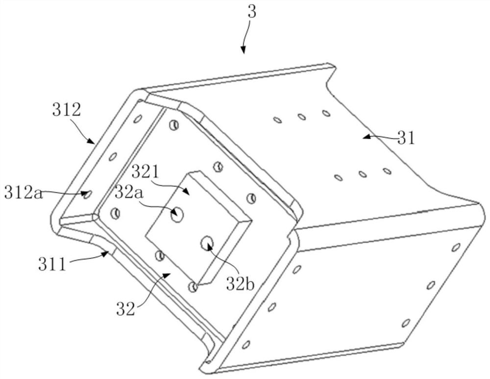
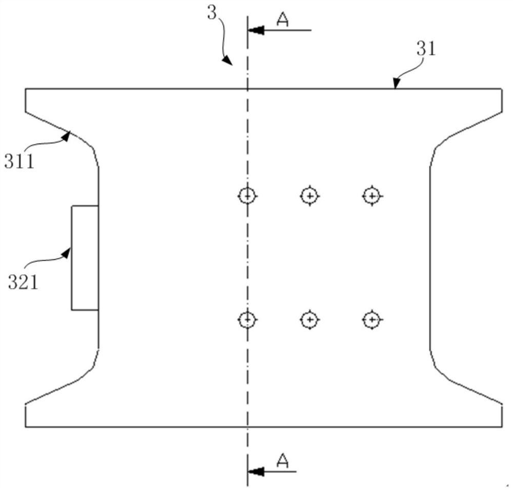
[0048] Please refer to Figure 2-9 , figure 2 It is the structural representation of auxiliary beam 3 in embodiment 1; image 3 for figure 2 main view of Figure 4 for image 3 right view of Figure 5 for Figure 4 left view of Image 6 for image 3 top view of Figure 7 for image 3 A-A sectional view; Figure 8 for Figure 5 B-B direction view; Figure 9 It is the C-C direction view of Figure 5.

[0049] like figure 2 , 7 As shown, the auxiliary beam 3 in this embodiment includes a casing 31 forming a closed cavity, and a partition 313 is arranged in the cavity of the casing 31, and the partition 313 divides the cavity into a first cavity 3a and a second cavity 3b. like figure 2 As shown, the housing 31 in Embodiment 1 is roughly square in shape, image 3 shows the top of the housing 31, image 3 The upper and lower sides of the middle housing 31 are respectively the front and rear sides of the housing 31, and the front and rear sides are the front an...

Embodiment 2

[0063] Please refer to Figure 10-16 , Figure 10 It is the front view of auxiliary beam 3 in embodiment 2; Figure 11 is the right view of Figure 10; Figure 12 for Figure 10 left view of Figure 13 for Figure 10 top view of Figure 14 for Figure 10 A-A sectional view of A-A; Figure 15 for Figure 12 B-B direction view; Figure 16 for Figure 12 C-C direction view.

[0064] The structure of the auxiliary beam 3 in the second embodiment is basically the same as that in the first embodiment, and only the differences will be described below, and the rest of the parts are the same and will not be repeated here. The difference is that in Embodiment 2, the first chamber 3a and the second chamber 3b of the housing 31 are not provided with inner linings. At this time, in order to facilitate the connection with external components, the special connection seat provided is no longer a sealed box, but Figure 14-16 The connection seat structure shown in.

[0065]The con...


PUM


Abstract

The invention discloses an auxiliary beam of a bogie. The auxiliary beam comprises a shell forming a closed inner cavity, the shell comprises a partition plate arranged in the inner cavity, the partition plate divides the inner cavity into a first cavity and a second cavity, and the shell is further provided with an auxiliary beam which penetrates through the inside and the outside and is provided with a first air chamber interface and a second air chamber interface that are respectively communicated with the first cavity and the second cavity; the shell is further provided with a first differential pressure valve connector and a second differential pressure valve connector which penetrate through the inside and the outside and are communicated with the first cavity and the second cavity respectively. According to the auxiliary beam, the auxiliary beam of the bogie frame not only serves as a connecting piece for connecting the front cross beam and the rear cross beam, but also is divided into the first cavity and the second cavity at the same time and can be communicated with the inner cavities of the cross beams, so that the auxiliary beam serves as an additional air chamber of an air spring installed on the bogie frame, and the volume of the additional air chamber is increased. In addition, the auxiliary beam provides installation space for the differential pressure valve at the same time, so that the structure of the framework is compact.

Description

technical field [0001] The invention relates to the technical field of rail vehicles, in particular to an auxiliary beam of a bogie. Background technique [0002] At present, in rail vehicles, such as subways, EMUs, high-speed rail, etc., the beams of the bogie frame are basically made of metal, and the auxiliary beams of the bogies are part of the beams of the bogies, and the auxiliary beams are welded between the two beams. There is an empty spring in the middle of the side beam of the bogie, and the inner cavity of the side beam forms an additional air chamber for the air spring. When the volume is insufficient, an external bellows is also used as an additional air chamber, and the structure is relatively complicated. [0003] In addition, the metal beams have problems such as heavy structural weight and easy corrosion of metal materials. At the same time, the auxiliary beams and beams are formed by welding technology, and the auxiliary beams cannot be disassembled, which...

Claims


Application Information

Patent Timeline
IPC IPC(8): B61F5/52
CPCB61F5/52B61F5/523Y02T30/00
Inventor 丁叁叁葛继文孙琳陈东方肖鹏李雨蔚
Owner CRRC QINGDAO SIFANG CO LTD
Why Eureka
Try Eureka