
Bionic tracheal stent mounted in trachea

A tracheal stent and endotracheal technology, applied in the field of bionic stents, can solve problems such as stent fatigue fracture, and achieve the effects of reducing stress, reducing fatigue fracture, and prolonging service life

Active Publication Date: 2015-03-25
MICRO TECH (NANJING) CO LTD
View PDF12 Cites 3 Cited by
  • Summary
  • Abstract
  • Description
  • Claims
  • Application Information

AI Technical Summary

Problems solved by technology

[0002] Existing stents are integrally braided or carved with nickel-titanium alloy materials, and the cross-section is a cylindrical structure. Therefore, if the stress points on the circumference are evenly distributed, the entire stent will expand when it is squeezed and contracted in the radial direction. Long, the fatigue strength can meet the needs of clinical use period (such as esophagus, intestinal tract, biliary tract stent, etc.), but according to the physiological and anatomical structure of the trachea, it has a layer of cricothyroid membrane inside and about 3 / 4 circle of cricoid cartilage on the outside When the trachea is squeezed and contracted by the esophagus when eating or coughed, the diameter of the cricoid cartilage will not change and shrink, only the cricothyroid membrane will shrink in the part that is not covered by the cricoid cartilage, and when the cylindrical stent is squeezed and deformed , instead of being elongated as a whole, and the circumference is in a state where the diameter of the overall outer circle becomes smaller, but it will receive lateral extrusion force, while the cricoid cartilage only limits the change of the diameter of the stent, making the stent change from a circular (full moon shape) ) into a crescent shape, the part of the bracket that contacts the edge of the cricoid cartilage will bend, resulting in a stress change perpendicular to the tangential direction, resulting in fatigue fracture of the bracket

Method used

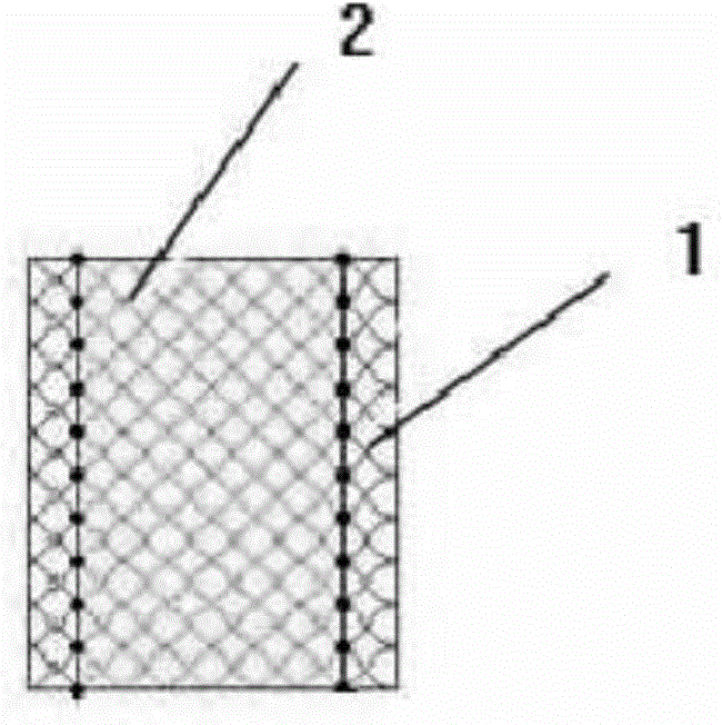

Image

  • Bionic tracheal stent mounted in trachea
  • Bionic tracheal stent mounted in trachea
  • Bionic tracheal stent mounted in trachea

Examples


Embodiment Construction

[0014] The present invention will be described in detail below in conjunction with the accompanying drawings.

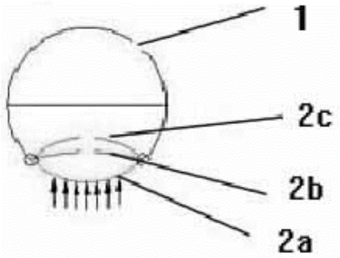
[0015] Such as figure 1 , the present invention includes a stent body 1, and the part of the stent body 1 corresponding to the tracheal cricothyroid membrane is opened with a non-closed structure 2, wherein the stent body 1 and the non-closed structure 2 are sutured by hinges. Specifically, as figure 2 , wherein the stent body 1 is a 3 / 4 type non-closed ring stent, and the flexible connecting stent 2a corresponds to the part of the tracheal cricothyroid membrane, and will bend to the inside of the stent body 1 to the position 2b or 2c when under pressure.

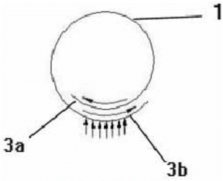
[0016] Such as image 3 , including a bracket body 1, an inner soft bracket 3a and an outer soft bracket 3b, the inner soft bracket 3a is connected to one end of the bracket body and extends inward, and the outer soft bracket 3b is connected to the other end of the bracket body 1 and extends outward and is conn...


PUM


Abstract

The invention discloses a bionic tracheal stent mounted in a trachea. The bionic tracheal stent comprises a stent body. The portion, corresponding to a cricothyroid membrane of the trachea, of the stent body is of a non-closed structure. The bionic tracheal stent has the advantages that the non-closed structure is arranged at the portion, corresponding to the cricothyroid membrane of the trachea of a human body, of the stent body, an arc-shaped structure made of a soft material is produced or two ends of the stent body extend in a staggered mode to enable the tracheal stent to form a helical structure, and the arc-shaped structure or the helical stent bends towards the interior of the stent body to reduce stress effect when the trachea is squeezed to contract, so that diameter change of the tracheal stent is limited, fatigue breakage of the stent due to stress contraction is reduced, and service life of the tracheal stent is prolonged.

Description

technical field [0001] The invention relates to a bionic support, in particular to a bionic trachea support installed in the trachea. Background technique [0002] Existing stents are integrally braided or carved with nickel-titanium alloy materials, and the cross-section is a cylindrical structure. Therefore, if the stress points on the circumference are evenly distributed, the entire stent will expand when it is squeezed and contracted in the radial direction. Long, the fatigue strength can meet the needs of clinical use period (such as esophagus, intestinal tract, biliary tract stent, etc.), but according to the physiological and anatomical structure of the trachea, it has a layer of cricothyroid membrane inside and about 3 / 4 circle of cricoid cartilage on the outside When the trachea is squeezed and contracted by the esophagus when eating or coughed, the diameter of the cricoid cartilage will not change and shrink, only the cricothyroid membrane will shrink in the part t...

Claims


Application Information

Patent Timeline
IPC IPC(8): A61F2/88
Inventor 金发光冷德嵘党军潘长网刘春俊
Owner MICRO TECH (NANJING) CO LTD
Learn More