Supercharge Your Innovation With Domain-Expert AI Agents!

a cupping device

A cupping device and tank body technology, which is used in suction containers, suction devices, physical therapy, etc., can solve the problems of tank body deformation, troublesome operation by operators, and difficult to accurately control, and achieve precise adjustment of strength and high one-way valve. Switching efficiency, strong negative pressure adsorption effect

Active Publication Date: 2016-05-18
WUHAN HINET TECH
View PDF9 Cites 0 Cited by
  • Summary
  • Abstract
  • Description
  • Claims
  • Application Information

AI Technical Summary

Problems solved by technology

[0002] At present, the existing cupping device includes a glass jar body, a plastic interface located at the upper end of the glass jar body, and a vacuum air gun connected to the plastic interface. The common cupping device uses a vacuum gun to cooperate with the jar body during operation. The gun pumps out the air and adsorbs on the surface of the human skin. The structure of the cupping device is complicated, and it is troublesome for the operator to operate.
Because the material of the tank body is glass or plexiglass, it will feel relatively stiff after being absorbed on the skin, so most of the human skin will feel pain after being absorbed, and when it is used on some small or uneven parts of the human body, ordinary cupping Due to the rigidity of the material, it is difficult to adsorb on the human skin, let alone achieve the expected conditioning effect
[0003] The ordinary silicone cupping device, although it can solve the pain caused by the above-mentioned adsorption and the problem that it is difficult to adsorb on uneven parts, it needs to discharge the air in the tube in advance, align the adsorption point and then adsorb the tank body on the body surface. It is labor-intensive and easy to get tired by pinching and squeezing the tank body. For people with hand disabilities, it is difficult to realize the adsorption and exhaust operation, which affects the effect of accurate positioning and pinpointing of acupoints, thus affecting the final actual treatment effect.
If the tank body is too soft, the tank body will be seriously deformed due to the negative pressure inside the tank, which will greatly reduce the adsorption force and cupping effect; if the tank body is tough enough, it will require a higher extrusion force for exhaust, and the operation will be laborious. Difficult to control precisely and even more difficult for people with hand disabilities
[0004] In the prior art, there are literatures on the application of one-way valves to cupping devices, but almost all one-way valves use rigid structures, complex structures, large volumes, and often require external air pumps to operate, not to mention labor-saving and high-efficiency.
The one-way valve with rigid structure cannot be directly applied to the flexible silicone cupping device, and there is no way to get technical inspiration from the structural details of the valve body

Method used


Image

  • a cupping device
  • a cupping device
  • a cupping device

Examples


Embodiment Construction

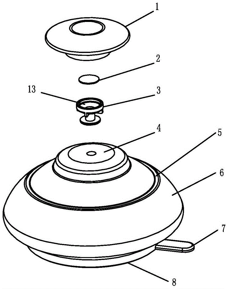
[0017] Below in conjunction with accompanying drawing and embodiment the present invention is further described: as figure 1 , the cupping device includes a silicone tank body 6 with a tank bottom 4 and an open tank mouth 8, and the tank body 6 of the cupping device is provided with a one-way air valve that can only be exhausted outside the tank.

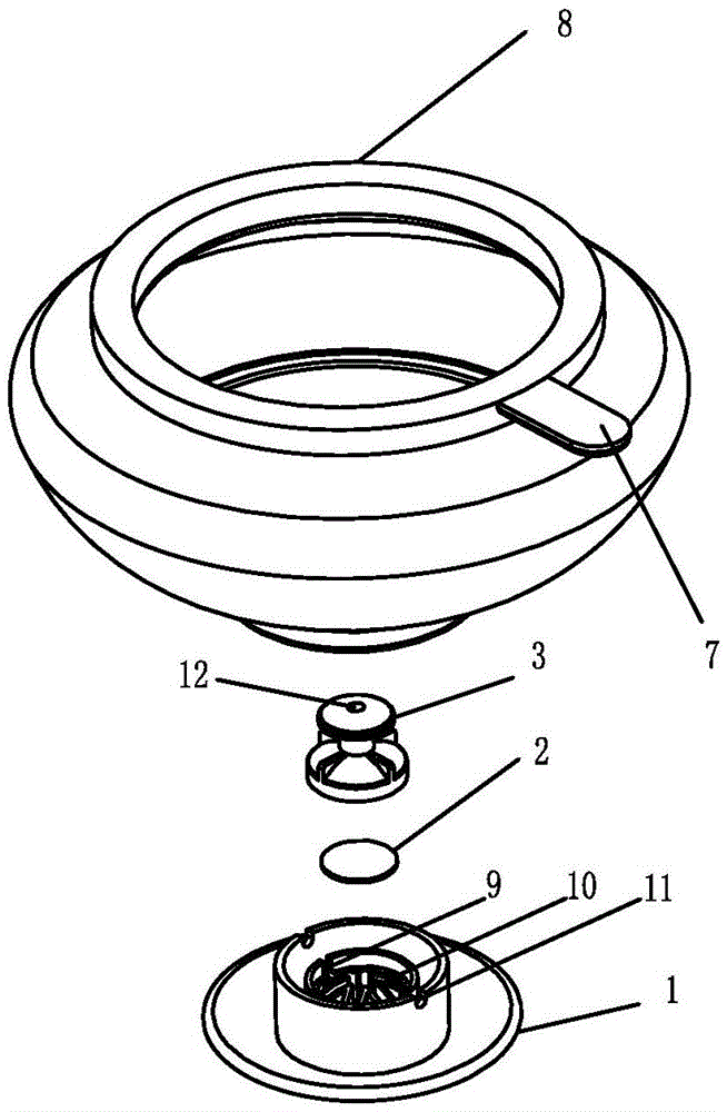
[0018] Such as figure 2 , 3 , as an optimized solution, the one-way air valve is arranged at the bottom 4 of the cupping device, and a valve cap 1 is arranged outside the one-way air valve. Further, the one-way air valve includes a valve body 3, a sealing sheet 2, and a support frame 10 arranged sequentially from the inside to the outside of the tank, the sealing sheet 2 covers the valve body 3, and the support frame 10 is connected to the The outer surface of the sealing sheet 2 is in contact.

[0019] Such as Figure 4 , for the above embodiments, the support frame 10 is provided with a bonnet 1 outside, or the support frame ...


PUM


Abstract

A portable and labor-saving cupping device comprises a cup body (6). The cup body (6) is made of a silica gel material and is provided with a one-way air valve; air in the cup body only can be exhausted outwards by the one-way air cavity; a cup lifting handle (7) is fixedly arranged on the cup body and on the outer side of a cup opening (8); and an easily pressed wrinkle (5) which facilitates extrusion exhausting is arranged on the outer periphery of the one-way air valve of the cup body. During cupping of the cupping device, a circumstance that negative pressure is generated with the aid of flame is avoided, and the portable and labor-saving cupping device is convenient to carry. Because an absorbing opening and the cup body are soft, a patient feels comfortable when cured by the cupping device; the portable and labor-saving cupping device can be absorbed on an uneven portion of the surface of the body of the patient, and is quite easy and convenient to operate; and after the portable and labor-saving cupping device is leisurely aligned with to a portion, which is required to be absorbed, of the body of the patient, a high negative pressure absorption effect can be achieved by pressing a bonnet on the bottom of the cup body. Advance manual extrusion exhausting is not required; and the bonnet is matched with the easily pressed wrinkle, the toughness of the cup body can be improved, and a high negative pressure absorption effect is achieved.

Description

technical field [0001] The invention relates to a medical and health product, in particular to a cupping device. Background technique [0002] At present, the existing cupping device includes a glass jar body, a plastic interface located at the upper end of the glass jar body, and a vacuum air gun connected to the plastic interface. The common cupping device uses a vacuum gun to cooperate with the jar body during operation. The gun sucks out the air and is adsorbed on the surface of the human skin. The structure of the cupping device is complicated, and it is cumbersome for the operator to operate. Because the material of the tank body is glass or plexiglass, it will feel relatively stiff after being absorbed on the skin, so most of the human skin will feel pain after being absorbed, and when it is used on some small or uneven parts of the human body, ordinary cupping Due to the rigidity of the material, it is difficult for the device to be adsorbed on human skin, and it is...

Claims


Application Information

Patent Timeline
Patent Type & Authority Patents(China)
IPC IPC(8): A61M1/00A61H9/00
CPCA61H9/0057A61M1/0003
Inventor 朱亚玲李芳远
Owner WUHAN HINET TECH
Features
  • R&D
  • Intellectual Property
  • Life Sciences
  • Materials
  • Tech Scout
  • Unparalleled Data Quality
  • Higher Quality Content
  • 60% Fewer Hallucinations
Learn More