Spiral-flow filter connector

A filter joint and swirl type technology, which is applied in the field of swirl filter joints, can solve the problems of high-efficiency filtration and low flow resistance of pipe joints, and achieve high safety, improved stability, and improved filtration quality.

Inactive Publication Date: 2015-03-25
CHONGQING WEST LINE TECH
View PDF8 Cites 2 Cited by
  • Summary
  • Abstract
  • Description
  • Claims
  • Application Information

AI Technical Summary

Problems solved by technology

[0011] The technical problem to be solved by the present invention is: to overcome the technical problem that the pipe joints in t

Method used


Image

  • Spiral-flow filter connector
  • Spiral-flow filter connector
  • Spiral-flow filter connector

Examples


Embodiment Construction

[0035] The present invention is described in further detail now in conjunction with accompanying drawing. These drawings are all simplified schematic diagrams, which only illustrate the basic structure of the present invention in a schematic manner, so they only show the configurations related to the present invention.

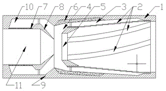
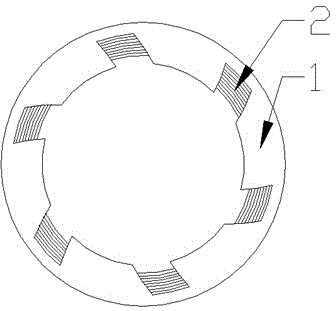
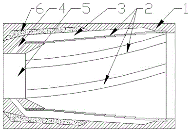
[0036] like figure 1 As shown, the present invention is a swirl filter joint, including a swirl separation part and a confluence separation part, the swirl separation part and the confluence separation part communicate with each other, and the swirl separation part includes a hollow circular The cylindrical shell A1, the two ends of the cylindrical shell A1 are provided with inlet and outlet ports, and the inner wall of the cylindrical shell A1 is provided with six swirl drainage grooves 2, and the swirl drainage grooves 2 The path relative to the axis of the cylindrical shell A1 is spirally arranged, and a filter screen is arranged in the swirl drainage groo...


PUM


Abstract

The invention relates to a spiral-flow filter connector. The spiral-flow filter connector comprises a spiral-flow separation part and a confluence separation part, wherein the spiral-flow separation part is used for rotating a fluid mainly by virtue of a main body with a spiral spiral-flow groove, so that foreign matter in different masses can be separated, then the fluid is secondarily separated and filtered by a separation assembly with a diverging opening in the confluence separation part, twice separation of the fluid can be realized through a simple structure, and the spiral-flow filter connector is convenient to install and low in manufacturing cost.

Description

technical field [0001] The invention relates to a swirling filter joint, in particular to a liquid joint capable of filtering trace impurities and irrelevant mixtures. Background technique [0002] In many fluid equipments that require high water quality, such as steam drums in boilers, distillers, and some chemical equipment, it is not only often necessary to filter water, but also these equipments often produce Scale, especially at the pipe joints, is particularly prone to blockage due to scaling or dirt accumulation. Whether it is impurities or blockage, it will bring certain safety hazards to these pressure reaction equipment; [0003] Therefore, at the joints of these equipment with high water quality requirements, it is necessary to install some filter components that can not only have a filtering effect, but also ensure a certain fluid permeability; [0004] Among them, ZL201320354014.4 proposes a pipeline filter joint, which has relatively high requirements for the ...

Claims


Application Information

Patent Timeline
IPC IPC(8): B01D36/04
Inventor 钱国东
Owner CHONGQING WEST LINE TECH
Why Eureka
Try Eureka