An oil fume collection device

A collection device and oil fume technology, which is applied in the direction of oil fume removal, household heating, lighting and heating equipment, etc., can solve the problems of unreasonable structure setting, complex composition and low oil fume concentration of the collection and adsorption device, and achieve high concentration of key components of oil fume , high detection accuracy and improved accuracy

Active Publication Date: 2015-07-29
GUANGZHOU ZHENGHONG TECH DEV
View PDF4 Cites 0 Cited by
  • Summary
  • Abstract
  • Description
  • Claims
  • Application Information

AI Technical Summary

Problems solved by technology

This kind of electrostatic oil fume purifier also has the following problems: when the working capacity of the purifier reaches saturation, it is necessary to clean the plates used to absorb oily particles; otherwise, the purifier will lose its purifying ability
However, due to the complex composition of the oil fume itself, the physical and chemical properties of the adsorbed oil particles are not easy to detect, so it is difficult to produce a very effective method for testing the purification ability of the electrostatic oil fume purifier. At present, there are two detection methods, one is absorbance method, and the other is the illumination method. The structure of the collection and adsorption device used by these two methods to collect oil fume samples is unreasonable. The data collected by the collection and adsorption device has a great relationship with the flow rate, and the data is unstable; The volume of the collected gas; in addition, the concentration of the adsorbed oil fume is small and not concentrated, so the accuracy of the test results is not high enough

Method used


Image

  • An oil fume collection device

Examples


Embodiment 1

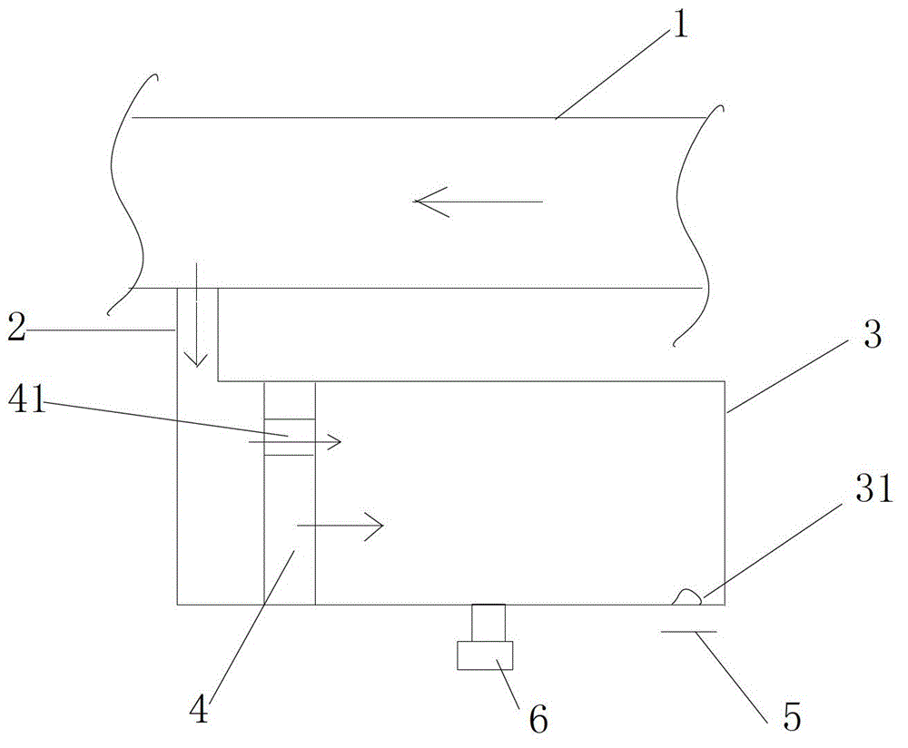
[0024] see figure 1 , the oil fume collecting device of the present invention comprises the oil fume collecting box 3 arranged on the side of the flue 1, the entrance of the oil fume collecting box 3 is connected with the bypass of the flue through the pipeline 2; the oil fume collecting box 3 is provided with a piston 4 near the entrance , the piston 4 is provided with an air intake through hole 41, and the oil fume collection box is also provided with an exhaust fan 6, which is used to suck the oil fume in the flue into the casing of the oil fume collection box; The air outlet hole 31, through which the oil fume sucked into the oil fume collection box is discharged to the outside, is sprayed onto the adsorption medium 5 for subsequent detection.

[0025] When the oil fume collection device of this embodiment is in use, the exhaust fan 6 works, and the oil fume gas in the flue 1 enters the oil fume collection box through the pipeline 2 and the air intake hole 41 on the piston...

Embodiment 2

[0027] Different from Embodiment 1, the oil fume collection device in this example further includes a controller for controlling the ventilation rate of the ventilation mechanism according to a preset control strategy. The rest are the same as those in Embodiment 1, and will not be repeated here.


PUM


Abstract

The invention discloses an oil smoke collection device. The oil smoke collection device comprises an oil smoke collection box which is communicated with a flue through a bypass, wherein a piston is arranged at an oil smoke inlet of the oil smoke collection box; an air inlet is formed in the piston; and a box body of the oil smoke collection box is provided with an air ventilation mechanism which is used for sucking oil smoke gas in the flue through the air inlet in the piston, and also an air outlet which is used for exhausting the oil smoke gas to the outside. The oil smoke collection device is provided with the piston type oil smoke collection box body which is used for collecting the oil smoke gas, so that the volume of the sucked oil smoke gas is constant, and is not influenced by the flowing speed of flue gas; and the sucked oil smoke gas can be compressed and then exhausted through the piston for concentration detection, so that the detection accuracy of subsequent oil smoke concentration is high.

Description

technical field [0001] The invention relates to the field of oil fume purifiers, in particular to an oil fume collection device capable of improving the detection accuracy of oil fume concentration. Background technique [0002] At present, catering establishments can be seen everywhere, and these places will inevitably produce a large amount of oily fumes during the cooking process, which will have a great impact on the production and life of surrounding enterprises and residents. For this reason, the environmental protection department requires catering institutions to install and use oil fume purifiers to reduce the impact of oil fume on the surrounding environment. [0003] At present, the most used and effective oil fume purifiers are mainly electrostatic oil fume purifiers. Its working principle is: the polarized area of ​​the purifier polarizes or charges the oil particles in the oil fume, making them charged. , and then let the charged oil particles pass through the...

Claims


Application Information

Patent Timeline
Patent Type & Authority Patents(China)
IPC IPC(8): F24C15/20
Inventor 谷育钢黄坚周文博
Owner GUANGZHOU ZHENGHONG TECH DEV
Why Eureka
Try Eureka