
Deburring machine dust cover

A technology of deburring machine and dust cover, which is applied in the direction of removing smoke and dust, chemical instruments and methods, cleaning methods and utensils, etc., can solve the problems of quality influence of casting billet, unsafe equipment maintenance and environmental pollution, etc., so as to shorten the maintenance period. The effect of working time, avoiding dust leakage, and simple hook replacement

Active Publication Date: 2016-09-14
武汉钢铁有限公司
View PDF8 Cites 0 Cited by
  • Summary
  • Abstract
  • Description
  • Claims
  • Application Information

AI Technical Summary

Problems solved by technology

[0003] 1. There is no inclined deflector above the hopper, and the removed burrs are easy to accumulate under the slab, thereby scratching the lower surface of the slab and having a great impact on the quality of the slab;
[0004] 2. Most of the burrs fall directly on the hook of the hopper, making it difficult to hook and dump the hopper;
[0005] 3. Since there is no iron dust collection device, a large amount of dust leaks out during the deburring process, causing great environmental pollution, and the dust accumulates on the equipment, which is easy to slip and fall, causing unsafe factors for equipment maintenance;
[0006] 4. It is difficult to recover burrs and dust, resulting in a lot of cost waste

Method used


Image

  • Deburring machine dust cover
  • Deburring machine dust cover
  • Deburring machine dust cover

Examples


Embodiment Construction

[0031] Below in conjunction with accompanying drawing and specific embodiment the present invention is described in further detail:

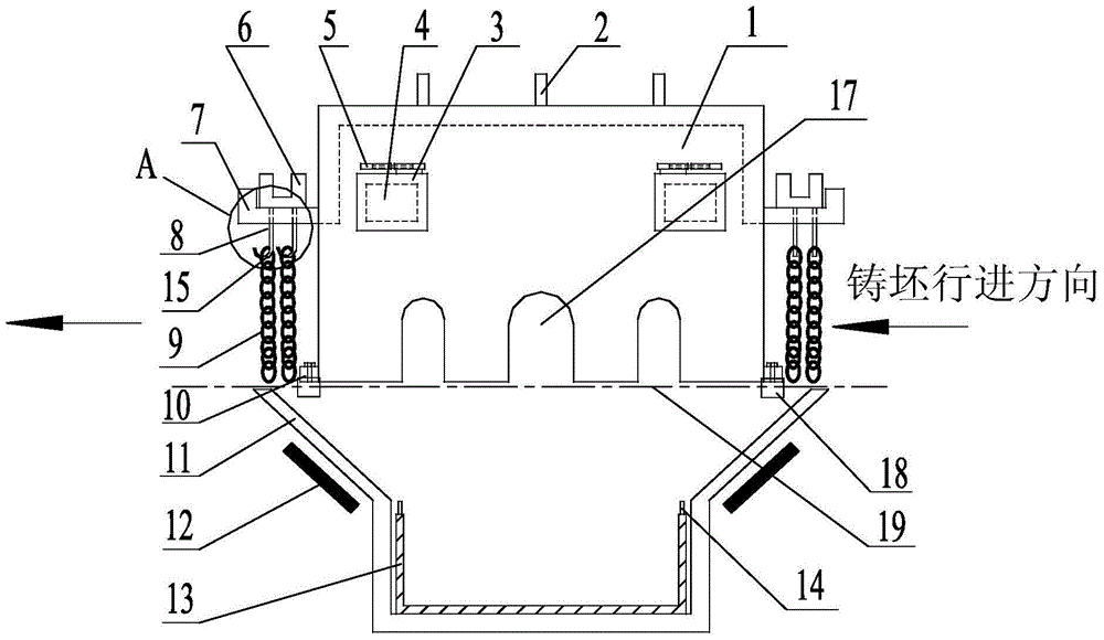
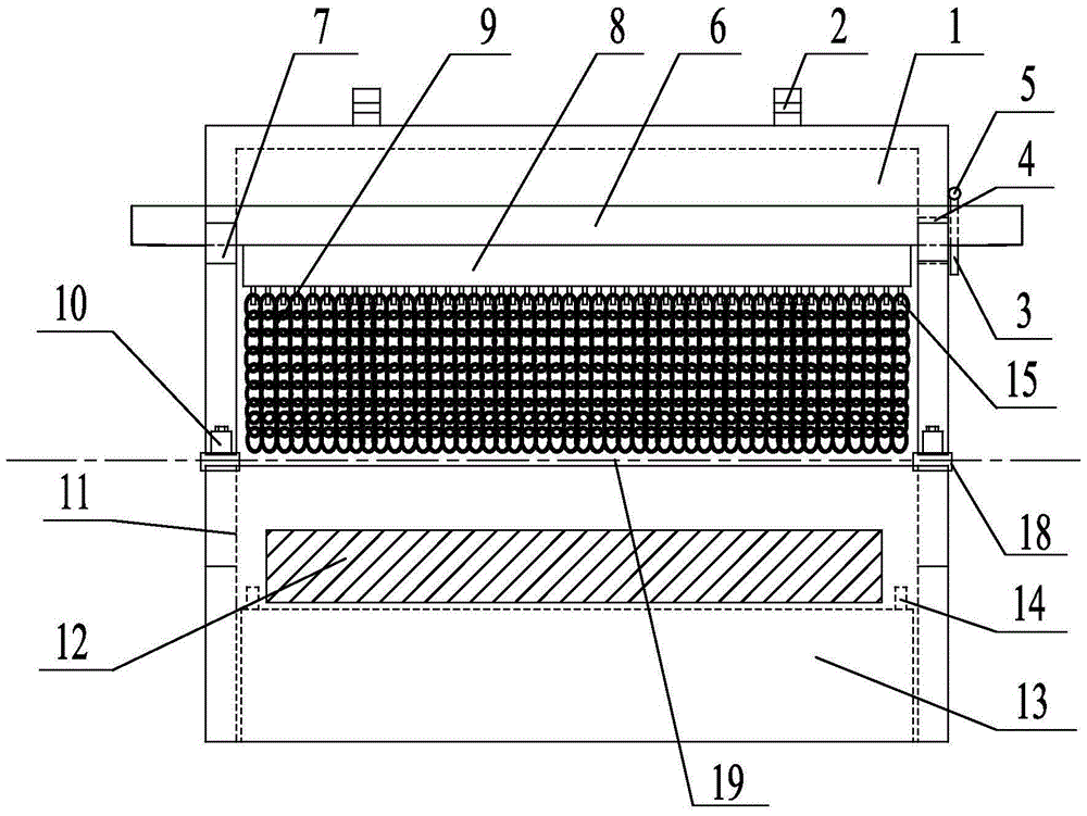
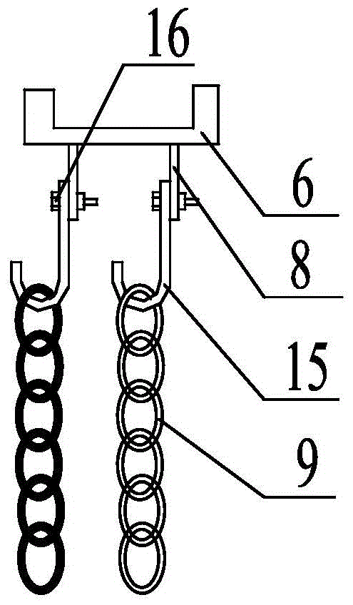
[0032] Such as Figure 1~3 The shown deburring machine dust cover includes a protective cover 1 with an opening at the bottom (the protective cover 1 is composed of five steel plates, and the bottom is in an open state), and the protective cover 1 is fixed on the foundation 18 through a positioning seat 10. Both sides of the slab input end of the protective cover 1 and both sides of the slab output end are fixed with support frames 7, and concave rods 6 are placed on the support frames 7 on both sides of the slab input end of the protective cover 1, and the protective cover 1 Concave rods 6 are also placed on the support frames 7 on both sides of the output end of the slab. The bottom ends of the above two concave rods 6 are provided with a plurality of hanging chains 9, and a diversion groove is provided under the protective cover 1. 11 (a div...


PUM


Abstract

The invention discloses a dustproof cover of a deburring machine. The dustproof cover comprises a protection cover with an opening in the bottom. The protection cover is fixed to foundations through positioning bases. Supporting frames are fixed to the two sides of the casting blank input end of the protection cover and the two sides of the casting blank output end of the protection cover respectively. A U-shaped rod is placed on the supporting frames on the two sides of the casting blank input end of the protection cover. A U-shaped rod is placed on the supporting frames on the two sides of the casting blank output end of the protection cover as well. A plurality of hanging chains are arranged at the bottom end of each U-shaped rod. A diversion tank is arranged below the protection cover and is located below a casting blank roll gang. Electromagnetic plates are arranged on the side walls of the diversion tank. A hopper is arranged at the bottom of the diversion tank. Installation holes matched with a roll of the casting blank roll gang are formed in the bottoms of the two sides of the protection cover. A closed area is formed in the slab deburring area through the protection cover and other devices, multiple layers of whole curtains are composed of hooks and hanging chains, and collision caused to the protection cover after casting blanks deform is avoided.

Description

technical field [0001] The invention relates to the technical field of iron and steel smelting equipment, in particular to a deburring machine dust cover. Background technique [0002] Before the present invention, only a hopper was designed under the deburring machine, and there was no dust cover and dust collection device, which mainly had the following problems: [0003] 1. There is no inclined deflector above the hopper, and the removed burrs are easy to accumulate under the slab, thereby scratching the lower surface of the slab and having a great impact on the quality of the slab; [0004] 2. Most of the burrs fall directly on the hook of the hopper, making it difficult to hook and dump the hopper; [0005] 3. Since there is no iron dust collection device, a large amount of dust leaks out during the deburring process, causing great environmental pollution, and the dust accumulates on the equipment, which is easy to slip and fall, causing unsafe factors for equipment ma...

Claims


Application Information

Patent Timeline
Patent Type & Authority Patents(China)
IPC IPC(8): B08B15/02
CPCB08B15/02B22D11/122B22D11/1265
Inventor 刘洋严开勇鲁新义胡念慈陈玮吴英杨志婷钟毅李华夏江涛
Owner 武汉钢铁有限公司
Learn More