
Bending device for full-automatic welding machine for volume control piece

A fully automatic welding and volume control technology, which is applied in manufacturing tools, metal processing equipment, forming tools, etc., can solve the problems of low production efficiency, manpower consumption, and increased processing time, so as to improve production efficiency, reduce personnel operations, shorten The effect of processing time

Active Publication Date: 2015-03-25
SUZHOU JINYIKANG AUTOMATION EQUIP
View PDF4 Cites 0 Cited by
  • Summary
  • Abstract
  • Description
  • Claims
  • Application Information

AI Technical Summary

Problems solved by technology

[0002] At present, the demand for mobile phones is constantly increasing, which requires a corresponding increase in the productivity of mobile phones to meet the market demand, resulting in the processing efficiency of mobile phone volume control parts must also be improved. For the single welding function of the welding machine, manual welding is required. The bracket and shrapnel are assembled and then welded, which consumes manpower and increases the processing time, resulting in low production efficiency. This requires a fully automatic welding machine that integrates feeding, assembly, welding and shearing to improve production efficiency. , so the components on the welding machine should also be automated

Method used


Image

  • Bending device for full-automatic welding machine for volume control piece
  • Bending device for full-automatic welding machine for volume control piece

Examples


Embodiment Construction

[0013] The present invention is described below in conjunction with accompanying drawing.

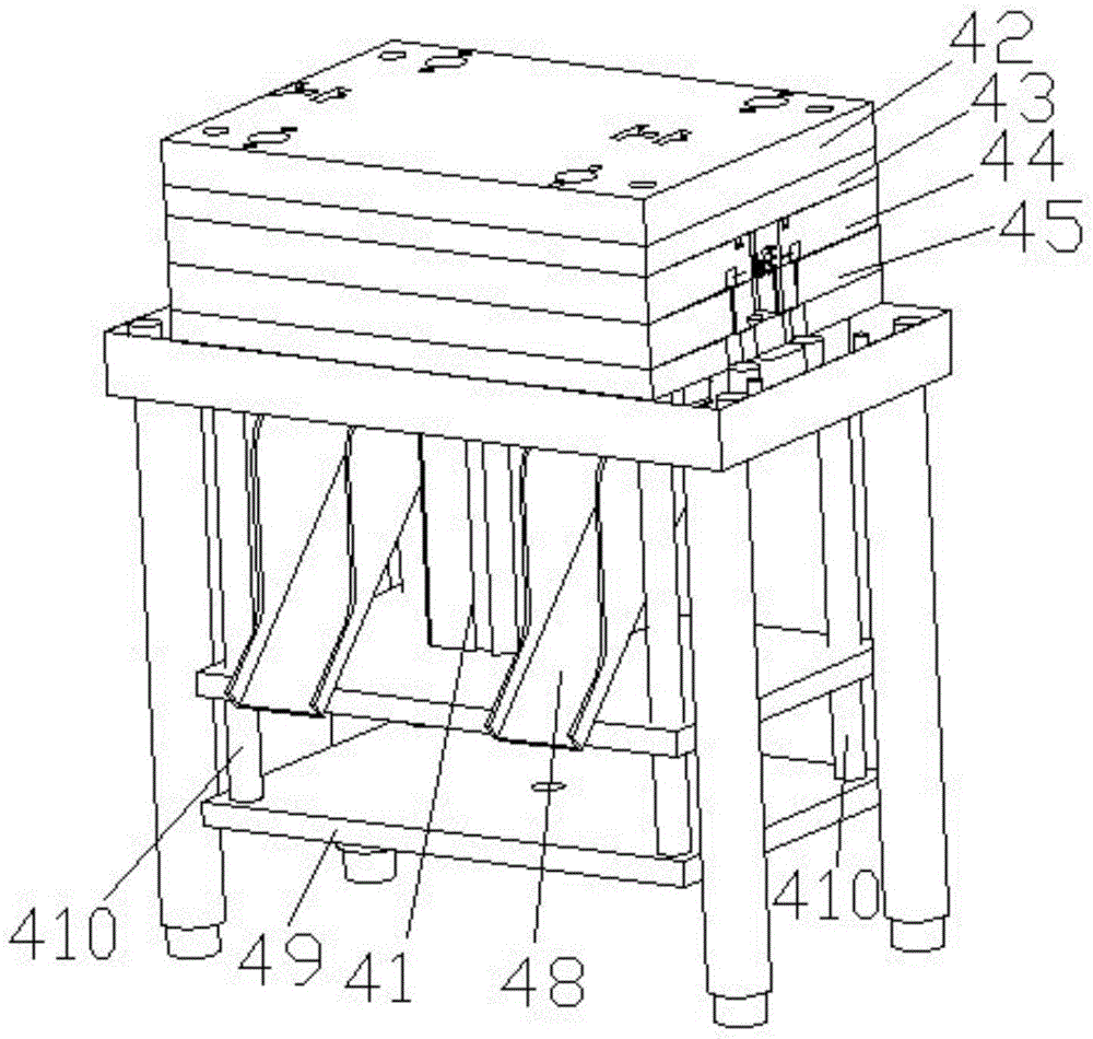
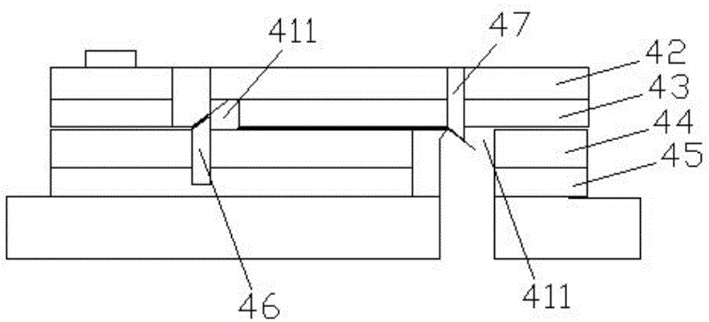
[0014] attached figure 1 It is the bending device used for the automatic welding machine of the volume control part according to the present invention, which includes a bending upper and lower driving device 41, a bending splint 42, a bending upper die 43, a bending stripping plate 44, and a bending lower die 45. Bending lower punch 46, bending upper punch 47, bending slide plate 48, top plate 49 and bending guide column 410; the bending splint 42, bending upper die 43, bending stripper 44 and the bending lower die 45 are stacked sequentially from top to bottom, the top plate 49 is connected to the bending splint 42 through the bending guide column 410, and the upper end of the bending lower punch 46 is a sharp angle inclined upward at 45°, so The lower end of the bending upper punch 47 is a sharp angle inclined downward at 45°, and the bending lower punch 46 and the bending upper punc...


PUM


Abstract

The invention discloses a bending device for a full-automatic welding machine for a volume control piece. The bending device comprises a bending vertical driving device, a bending clamp plate, an upper bending die, a bending stripper plate, a lower bending die, a lower bending punch, an upper bending punch, a bending material sliding plate, an ejector plate and a bending guide column. The bending clamp plate, the upper bending die, the bending stripper plate and the lower bending die are stacked from top to bottom in sequence, and the bending clamp plate and the upper bending die can be lifted upwards together so that a die opening state can be formed. The upper end of the lower bending punch is a tip inclined upwards by 45 degrees, and the lower end of the upper bending punch is a tip inclined downwards by 45 degrees. The bending vertical driving device drives the ejector plate to drive the bending clamp plate and the upper bending die to press down together through the bending guide column so that a die assembly state can be formed. The bending device automatically carries out bending and shearing on components welded by the welding machine, finished parts can be obtained directly, automation of the machine is realized, operation of staff is reduced, machining time is shortened, production cost is lowered, and production efficiency is improved.

Description

technical field [0001] The invention relates to a device used on a fully automatic welding machine to automatically bend and cut welded parts. Background technique [0002] At present, the demand for mobile phones is constantly increasing, which requires that the productivity of mobile phones should be increased accordingly to meet the market demand. As a result, the processing efficiency of mobile phone volume control components must also be improved. For the single welding function of the welding machine, manual welding is required. The bracket and shrapnel are assembled and then welded, which consumes manpower and increases the processing time, resulting in low production efficiency. This requires a fully automatic welding machine that integrates feeding, assembly, welding and cutting to improve production efficiency. , so the components on the welding machine should also be automated. Contents of the invention [0003] In view of the above-mentioned technical problems...

Claims


Application Information

Patent Timeline
IPC IPC(8): B21D5/04B21D37/10
CPCB21D5/06B21D37/10
Inventor 周光华
Owner SUZHOU JINYIKANG AUTOMATION EQUIP
Learn More