Upward bending correction mechanism

A technology of correction mechanism and die, applied in metal processing equipment, forming tools, manufacturing tools, etc., can solve the problems of easy scratching on product surface, low production efficiency, mold wear, etc., and achieve easy promotion, simple structure, and long mold. effect of life

Inactive Publication Date: 2015-03-25
WUXI MICRO RES
View PDF10 Cites 6 Cited by
  • Summary
  • Abstract
  • Description
  • Claims
  • Application Information

AI Technical Summary

Problems solved by technology

Generally, upward bending is more severe than downward bending, and it is difficult to bend upward to 90° in one step. In the prior art, the method of reducing the gap between the punch and die is usually used, which can effectively reduce the amount of rebound, but at this time the product The surface is easily scratched, the mold is severely worn, and the production efficiency is low

Method used


Image

  • Upward bending correction mechanism
  • Upward bending correction mechanism
  • Upward bending correction mechanism

Examples


Embodiment Construction

[0015] The specific implementation manner of the present invention will be described below in conjunction with the accompanying drawings.

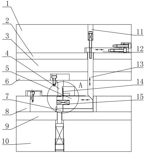
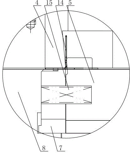
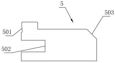
[0016] Such as figure 1 , figure 2 As shown, the upward bending correction mechanism of this embodiment includes an upper mold assembly and a lower mold assembly. The structure of the upper mold assembly is: including an upper mold base 1, and an upper mold backing plate 2 is sequentially installed under the upper mold base 1 , punch fixed plate 3 and stripping plate 6, and correcting punch 4 is installed on the stripping plate 6; The correction die 5 paired with the correction punch 4 is installed on the die fixing plate 8, the first wedge bar 12 is installed on the horizontal position of one end of the upper die base 1, and the second wedge rod 12 is installed on the upper die base 1 vertically through the bolt 11 and the spring. Slant wedge 13, the top of the first wedge 12 abuts against the upper end of the second wedge 13; the stru...


PUM


Abstract

The invention relates to an upward bending correction mechanism which comprises an upper die seat. An upper die component and a correction male die are sequentially arranged under the upper die seat. The upward bending correction mechanism further comprises a lower die seat, and a lower die component and a correction female die paired with the correction male die are sequentially arranged on the lower die seat. A first wedge rod is horizontally arranged at one end of the upper die seat. A second wedge rod is vertically arranged at one end of the upper die seat. The top end of the first wedge rod abuts against the upper end of the second wedge rod. A boss is arranged on the head portion of the left end of the correction female die, the left end face of the boss is provided with an inwards-concave slope, a spring groove is formed in the lower portion of the slope, and a wedged notch is formed in the right end of the correction female die. A groove opposite to the spring grove is dig in the middle of a female die fixing plate, and a spring is arranged in the groove and the spring groove. A workpiece is arranged between the correction male die and the correction female die, and the lower portion of the workpiece abuts against the top of a material lifting block. The upward bending correction mechanism can bend upwards the workpiece and adjust overdone bending, reduces bent scratches on the surface of a product, prolongs the service lives of the dies, and improves production efficiency.

Description

technical field [0001] The invention relates to the technical field of correcting molds, in particular to an upward bending correction mechanism. Background technique [0002] When the product is bent 90° once in the mold, because any metal material has bending resilience, the angle of the product after bending is greater than 90°, and the rebound angle of different materials is different, so it is difficult to meet the angle size required by the product design. In general, upward bending is more severe than downward bending, and it is difficult to bend upward to 90° in one step. In the prior art, the method of reducing the gap between the punch and die is usually used, which can effectively reduce the amount of rebound, but at this time the product The surface is easily scratched, the mold is severely worn, and the production efficiency is low. Contents of the invention [0003] In view of the shortcomings in the above-mentioned existing production technology, the applic...

Claims


Application Information

Patent Timeline
Patent Type & Authority Applications(China)
IPC IPC(8): B21D37/10B21D21/00
CPCB21D37/10B21D21/00
Inventor 张立山陈兆茂
Owner WUXI MICRO RES
Why Eureka
Try Eureka